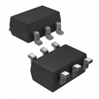
AO6420
60V N-Channel MOSFET
General Description
Product Summary
The AO6420 uses advanced trench technology to
provide excellent RDS(ON) and low gate charge. This
device is suitable for use as a load switch or in PWM
applications.
VDS (V) = 60V
ID = 4.2A (VGS = 10V)
RDS(ON) < 60mΩ (VGS = 10V)
RDS(ON) < 75mΩ (VGS = 4.5V)
TSOP6
Top View
D
Bottom View
Top View
D
1
6
D
D
2
5
D
G
3
4
S
G
S
Pin1
Absolute Maximum Ratings TA=25°C unless otherwise noted
Parameter
Symbol
Drain-Source Voltage
VDS
Gate-Source Voltage
VGS
TA=25°C
Continuous Drain
Current A,F
Pulsed Drain Current
TA=70°C
ID
B
V
Junction and Storage Temperature Range
20
-55 to 150
Symbol
Alpha & Omega Semiconductor, Ltd.
W
1.28
TJ, TSTG
t ≤ 10s
Steady-State
Steady-State
A
2.00
PD
TA=70°C
Maximum Junction-to-Lead C
±20
3.4
IDM
Thermal Characteristics
Parameter
Maximum Junction-to-Ambient A
Maximum Junction-to-Ambient A
Units
V
4.2
TA=25°C
Power Dissipation
Maximum
60
RθJA
RθJL
Typ
48
74
35
°C
Max
62.5
110
40
Units
°C/W
°C/W
°C/W
www.aosmd.com
�AO6420
N Channel Electrical Characteristics (TJ=25°C unless otherwise noted)
Symbol
Parameter
STATIC PARAMETERS
BVDSS
Drain-Source Breakdown Voltage
IDSS
Zero Gate Voltage Drain Current
Conditions
Min
ID=250µA, VGS=0V
5
Gate-Body leakage current
VDS=0V, VGS= ±20V
VGS(th)
Gate Threshold Voltage
VDS=VGS ID=250µA
1
ID(ON)
On state drain current
VGS=10V, VDS=5V
20
VGS=10V, ID=4.2A
TJ=125°C
VGS=4.5V, ID=3A
gFS
Forward Transconductance
VDS=5V, ID=4.2A
VSD
Diode Forward Voltage
IS=1A,VGS=0V
IS
Maximum Body-Diode Continuous Current
DYNAMIC PARAMETERS
Ciss
Input Capacitance
Coss
Output Capacitance
Crss
Reverse Transfer Capacitance
Rg
Gate resistance
VGS=0V, VDS=0V, f=1MHz
µA
100
nA
2.3
3
V
50
60
A
85
60
mΩ
75
mΩ
1
V
3
A
13
0.78
450
VGS=0V, VDS=30V, f=1MHz
Units
V
1
TJ=55°C
Static Drain-Source On-Resistance
Max
60
VDS=60V, VGS=0V
IGSS
RDS(ON)
Typ
S
540
pF
60
pF
25
pF
Ω
1.65
2
SWITCHING PARAMETERS
Qg(10V) Total Gate Charge
9.5
11.5
nC
Qg(4.5V) Total Gate Charge
4.3
5.5
nC
Qgs
Gate Source Charge
Qgd
Gate Drain Charge
tD(on)
Turn-On DelayTime
tr
Turn-On Rise Time
tD(off)
Turn-Off DelayTime
tf
trr
Turn-Off Fall Time
Qrr
VGS=10V, VDS=30V, ID=4.2A
VGS=10V, VDS=30V, RL=7Ω,
RGEN=3Ω
IF=4.2A, dI/dt=100A/µs
Body Diode Reverse Recovery Time
Body Diode Reverse Recovery Charge IF=4.2A, dI/dt=100A/µs
1.6
nC
2.2
nC
5.1
7
ns
2.6
4
ns
15.9
20
ns
2
3
ns
25.1
35
ns
nC
28.7
A: The value of R θJA is measured with the device mounted on 1in 2 FR-4 board with 2oz. Copper, in a still air environment with T A=25°C. The
value in any given application depends on the user's specific board design. The current rating is based on the t ≤ 10s thermal resistance rating.
B: Repetitive rating, pulse width limited by junction temperature.
C. The R θJA is the sum of the thermal impedence from junction to lead R θJL and lead to ambient.
D. The static characteristics in Figures 1 to 6 are obtained using
很抱歉,暂时无法提供与“AO6420”相匹配的价格&库存,您可以联系我们找货
免费人工找货- 国内价格 香港价格
- 3000+1.859103000+0.24168
- 9000+1.629039000+0.21177
- 国内价格 香港价格
- 1+7.769211+1.00998
- 10+4.8536310+0.63096
- 50+3.5565550+0.46234
- 100+3.13821100+0.40796
- 500+2.39958500+0.31194
- 国内价格
- 1+1.49600
- 100+1.15500
- 750+0.95810
- 1500+0.87120
- 3000+0.80850
- 国内价格
- 5+1.63988
- 50+1.29708
- 150+1.15031
- 500+0.96704
- 3000+0.76983