AONR36326C
30V N-Channel MOSFET
General Description
Product Summary
VDS
• Trench Power MOSFET technology
• Very Low RDS(ON) at 4.5V VGS
• Low Gate Charge
• High Current Capability
• RoHS and Halogen-Free Compliant
Applications
ID (at VGS=10V)
30V
12A
RDS(ON) (at VGS=10V)
< 9.8mΩ
RDS(ON) (at VGS=4.5V)
< 15.9mΩ
100% UIS Tested
100% Rg Tested
• DC/DC Converters in Computing, Servers, and POL
• Isolated DC/DC Converters in Telecom and Industrial
• See Note I
DFN 3x3 EP
Bottom View
Top View
D
Top View
Pin 1
S
S
S
1
8
D
2
7
3
6
D
D
G
4
5
D
G
S
Pin 1
Orderable Part Number
Package Type
Form
Minimum Order Quantity
AONR36326C
DFN 3X3 EP
Tape & Reel
5000
Absolute Maximum Ratings TA=25°C unless otherwise noted
Parameter
Drain-Source Voltage
Symbol
VDS
Gate-Source Voltage
VGS
TC=25°C
Continuous Drain
Current G
Pulsed Drain Current C
Avalanche Current C
Avalanche energy
Power Dissipation
L=0.05mH
TC=25°C
B
C
TA=25°C
Power Dissipation A
Junction and Storage Temperature Range
Thermal Characteristics
Parameter
Maximum Junction-to-Ambient A
Maximum Junction-to-Ambient A D
Maximum Junction-to-Case
Rev.1.2: April 2021
IAS
20
A
EAS
10
mJ
20.5
Steady-State
Steady-State
RqJA
RqJC
www.aosmd.com
W
8
3.1
W
2
TJ, TSTG
Symbol
t ≤ 10s
A
11
PDSM
TA=70°C
A
12
PD
TC=100°C
V
48
IDSM
TA=70°C
±20
12
IDM
TA=25°C
Continuous Drain
CurrentG
Units
V
12
ID
TC=100°C
Maximum
30
-55 to 150
Typ
30
60
5
°C
Max
40
70
6
Units
°C/W
°C/W
°C/W
Page 1 of 6
�AONR36326C 0
Electrical Characteristics (TJ=25°C unless otherwise noted)
Symbol
Parameter
STATIC PARAMETERS
BVDSS
Drain-Source Breakdown Voltage
Conditions
Min
ID=250μA, VGS=0V
Typ
30
Zero Gate Voltage Drain Current
IGSS
VGS(th)
Gate-Body leakage current
VDS=0V, VGS=±20V
Gate Threshold Voltage
VDS=VGS, ID=250mA
1
TJ=55°C
5
1.3
VGS=10V, ID=12A
nA
1.8
2.3
V
8
9.8
11
13.5
15.9
Static Drain-Source On-Resistance
VGS=4.5V, ID=10A
13
gFS
Forward Transconductance
VDS=5V, ID=12A
45
VSD
Diode Forward Voltage
IS=1A, VGS=0V
0.73
IS
Maximum Body-Diode Continuous Current
G
DYNAMIC PARAMETERS
Ciss
Input Capacitance
Coss
Output Capacitance
Crss
Reverse Transfer Capacitance
Rg
Gate resistance
VGS=0V, VDS=15V, f=1MHz
μA
±100
RDS(ON)
TJ=125°C
Units
V
VDS=30V, VGS=0V
IDSS
Max
mΩ
mΩ
S
1
V
12
A
540
pF
230
pF
30
pF
2
3
Ω
SWITCHING PARAMETERS
Qg(10V) Total Gate Charge
9
15
nC
Qg(4.5V) Total Gate Charge
4.3
7
nC
Qgs
Gate Source Charge
Qgd
Gate Drain Charge
tD(on)
Turn-On DelayTime
tr
Turn-On Rise Time
tD(off)
Turn-Off DelayTime
tf
trr
Turn-Off Fall Time
Qrr
f=1MHz
VGS=10V, VDS=15V, ID=12A
1
2.2
nC
1.7
nC
4
ns
3.5
ns
18
ns
3
ns
IF=12A, di/dt=500A/ms
9.7
Body Diode Reverse Recovery Charge IF=12A, di/dt=500A/ms
11.5
ns
nC
Body Diode Reverse Recovery Time
VGS=10V, VDS=15V, RL=1.25W,
RGEN=3W
A. The value of RqJA is measured with the device mounted on 1in 2 FR-4 board with 2oz. Copper, in a still air environment with T A =25°C. The Power
dissipation P DSM is based on R qJA t≤ 10s and the maximum allowed junction temperature of 150 °C. The value in any given application depends on
the user's specific board design.
B. The power dissipation P D is based on TJ(MAX)=150°C, using junction-to-case thermal resistance, and is more useful in setting the upper dissipation
limit for cases where additional heatsinking is used.
C. Single pulse width limited by junction temperature T J(MAX)=150°C.
D. The RqJA is the sum of the thermal impedance from junction to case R qJC and case to ambient.
E. The static characteristics in Figures 1 to 6 are obtained using 1ms turn-on/turn-off, please consult AOS FAE for proper product selection.
APPLICATIONS OR USES AS CRITICAL COMPONENTS IN LIFE SUPPORT DEVICES OR SYSTEMS ARE NOT AUTHORIZED. AOS DOES NOT
ASSUME ANY LIABILITY ARISING OUT OF SUCH APPLICATIONS OR USES OF ITS PRODUCTS. AOS RESERVES THE RIGHT TO MAKE
CHANGES TO PRODUCT SPECIFICATIONS WITHOUT NOTICE. IT IS THE RESPONSIBILITY OF THE CUSTOMER TO EVALUATE
SUITABILITY OF THE PRODUCT FOR THEIR INTENDED APPLICATION. CUSTOMER SHALL COMPLY WITH APPLICABLE LEGAL
REQUIREMENTS, INCLUDING ALL APPLICABLE EXPORT CONTROL RULES, REGULATIONS AND LIMITATIONS.
AOS' products are provided subject to AOS' terms and conditions of sale which are set forth at:
http://www.aosmd.com/terms_and_conditions_of_sale
Rev.1.2: April 2021
www.aosmd.com
Page 2 of 6
�AONR36326C
TYPICAL ELECTRICAL AND THERMAL CHARACTERISTICS
50
50
10V
4.5V
VDS=5V
4V
6V
40
40
30
ID (A)
ID (A)
30
3.5V
20
20
125°C
10
10
25°C
VGS=3V
0
0
0
1
2
3
4
0
5
1
16
4
5
1.6
Normalized On-Resistance
14
RDS(ON) (mW)
3
VGS (Volts)
Figure 2: Transfer Characteristics (Note E)
VDS (Volts)
Figure 1: On-Region Characteristics (Note E)
12
VGS=4.5V
10
8
VGS=10V
6
VGS=10V
ID=12A
1.4
1.2
1
VGS=4.5V
ID=12A
0.8
4
0
3
6
9
12
0
15
25
50
75
100
125
150
175
Temperature (°C)
Figure 4: On-Resistance vs. Junction Temperature
(Note E)
ID (A)
Figure 3: On-Resistance vs. Drain Current and Gate
Voltage (Note E)
10
25
ID=12A
1
20
125°C
0.1
125°C
15
IS (A)
RDS(ON) (mW)
2
0.01
25°C
10
0.001
25°C
5
0.0001
1E-05
0
2
4
6
8
10
VGS (Volts)
Figure 5: On-Resistance vs. Gate-Source Voltage
(Note E)
Rev.1.2: April 2021
www.aosmd.com
0.0
0.2
0.4
0.6
0.8
1.0
VSD (Volts)
Figure 6: Body-Diode Characteristics
(Note E)
Page 3 of 6
0
�AONR36326C
TYPICAL ELECTRICAL AND THERMAL CHARACTERISTICS
800
10
VDS=15V
ID=12A
Ciss
600
Capacitance (pF)
VGS (Volts)
8
6
4
400
Coss
200
2
Crss
0
0
0
2
4
6
8
0
10
10ms
RDS(ON)
limited
25
30
150
1.0
DC
1ms
10ms
Power (W)
ID (Amps)
20
TJ(Max)=150°C
TC=25°C
10ms
100ms
0.0
0.01
15
200
100.0
0.1
10
VDS (Volts)
Figure 8: Capacitance Characteristics
Qg (nC)
Figure 7: Gate-Charge Characteristics
10.0
5
TJ(Max)=150°C
TC=25°C
100
50
0.1
1
10
VDS (Volts)
VGS> or equal to 4.5V
Figure 9: Maximum Forward Biased
Safe Operating Area (Note F)
100
0
0.0001
0.001
0.01
0.1
1
10
100
Pulse Width (s)
Figure 10: Single Pulse Power Rating Junction-toCase (Note F)
ZqJC Normalized Transient
Thermal Resistance
10
D=Ton/T
TJ,PK=TC+PDM.ZqJC.RqJC
In descending order
D=0.5, 0.3, 0.1, 0.05, 0.02, 0.01, single pulse
RqJC=6°C/W
1
0.1
PDM
Single Pulse
Ton
T
0.01
1E-05
0.0001
0.001
0.01
0.1
1
10
100
Pulse Width (s)
Figure 11: Normalized Maximum Transient Thermal Impedance (Note F)
Rev.1.2: April 2021
www.aosmd.com
Page 4 of 6
0
�AONR36326C
30
15
25
12
Current rating ID (A)
Power Dissipation (W)
TYPICAL ELECTRICAL AND THERMAL CHARACTERISTICS
20
15
10
5
9
6
3
0
0
0
25
50
75
100
125
0
150
25
50
75
100
125
150
TCASE (°C)
Figure 13: Current De-rating (Note F)
TCASE (°C)
Figure 12: Power De-rating (Note F)
10000
TA=25°C
Power (W)
1000
100
10
1
1E-05
0.001
0.1
10
1000
Pulse Width (s)
Figure 14: Single Pulse Power Rating Junction-to-Ambient (Note H)
ZqJA Normalized Transient
Thermal Resistance
10
D=Ton/T
TJ,PK=TA+PDM.ZqJA.RqJA
1
In descending order
D=0.5, 0.3, 0.1, 0.05, 0.02, 0.01, single pulse
RqJA=70°C/W
0.1
PDM
Single Pulse
0.01
0.001
0.0001
Ton
0.001
0.01
0.1
1
T
10
100
1000
Pulse Width (s)
Figure 15: Normalized Maximum Transient Thermal Impedance (Note H)
Rev.1.2: April 2021
www.aosmd.com
Page 5 of 6
0
�AONR36326C
Figure
A: Charge
Gate Charge
Test Circuit
& Waveforms
Gate
Test Circuit
& Waveform
Vgs
Qg
10V
+
+ Vds
VDC
-
Qgs
Qgd
VDC
-
DUT
Vgs
Ig
Charge
Figure B:Resistive
ResistiveSwitching
Switching Test
Test Circuit
Circuit&&Waveforms
Waveforms
RL
Vds
Vds
Vgs
90%
+ Vdd
DUT
VDC
-
Rg
10%
Vgs
Vgs
td(on)
tr
td(off)
ton
tf
toff
Figure C:
UnclampedInductive
InductiveSwitching
Switching (UIS)
(UIS) Test
Unclamped
Test Circuit
Circuit&&Waveforms
Waveforms
L
2
EAR= 1/2 LIAR
Vds
BVDSS
Vds
Id
+ Vdd
Vgs
Vgs
I AR
VDC
-
Rg
Id
DUT
Vgs
Vgs
Figure
D: Recovery
Diode Recovery
Test Circuit
& Waveforms
Diode
Test Circuit
& Waveforms
Q rr = - Idt
Vds +
DUT
Vds -
Isd
Vgs
Ig
Rev.1.2: April 2021
Vgs
L
Isd
+ Vdd
t rr
dI/dt
I RM
Vdd
VDC
-
IF
Vds
www.aosmd.com
Page 6 of 6
0
�
很抱歉,暂时无法提供与“AONR36326C”相匹配的价格&库存,您可以联系我们找货
免费人工找货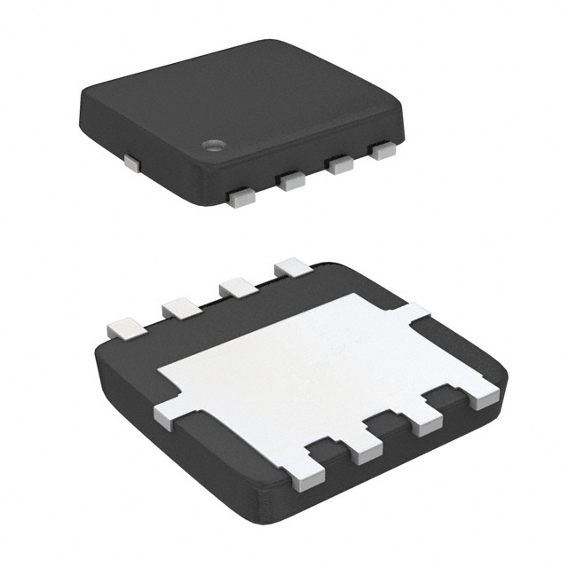


 工商网监
湘ICP备2023018690号
工商网监
湘ICP备2023018690号
