AOZ8204
Four-line TVS Diode Array
General Description
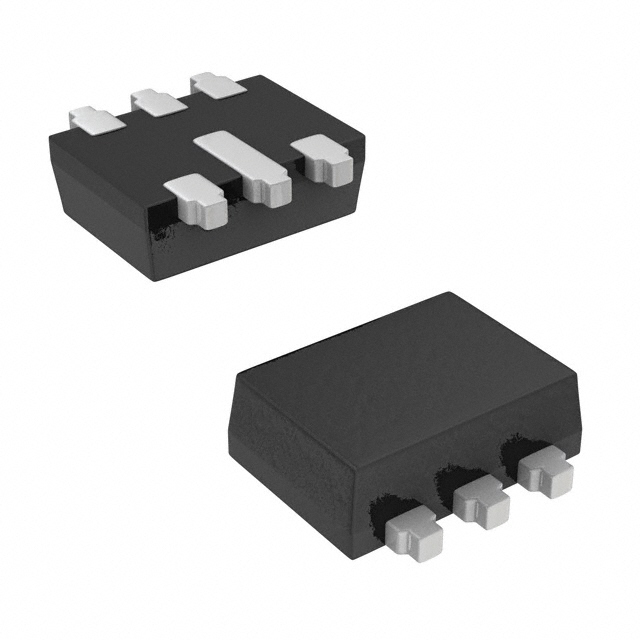
The AOZ8204 is a transient voltage suppressor diode array designed to protect data lines from high transient conditions and ESD. This device incorporates four TVS diodes in a single package. Due to the flexibility of the design, the package can be configured as a two channel bidirectional TVS array. During transient conditions, the TVS diodes direct the transient to ground. They may be used to meet the ESD immunity requirements of IEC 61000-4-2, Level 4 (±15kV air, ±8kV contact discharge). The AOZ8204 comes in an RoHS compliant SC-89 package and is rated over a -40°C to +85°C ambient temperature range. The very small 1.7 x 1.7 x 0.6mm SC-89 package makes it ideal for applications where PCB space is a premium. The small size and high ESD protection makes it ideal for protecting high speed video and data communication interfaces.
Features
●
● ● ● ● ●
ESD protection for high-speed data lines: – Exceeds: IEC 61000-4-2 (ESD) ±30kV (air), ±30kV (contact) – Human Body Model (HBM) ±30kV Small package saves board space Low insertion loss Protects four unidirectional or two bidirectional I/O lines Low clamping voltage Low operating voltage: 5.0V
Applications
● ● ● ● ● ●
Portable handheld devices Keypads, data lines Notebook computers Digital Cameras Portable GPS MP3 players
Typical Application
I/O1 I/O2 I/O3 I/O4
Pin Configuration
1 6
2
5
3
4
Unidirection Protection of Four Lines
Top View
I/O1 I/O2
3 4 2 5 1 6
Bidirection Protection of Two Lines
Rev. 1.3 March 2008
www.aosmd.com
Page 1 of 6
�AOZ8204
Ordering Information
Part Number
AOZ8204KI
Ambient Temperature Range
-40°C to +85°C
Package
SC-89
Environmental
RoHS Compliant
All AOS Products are offering in packaging with Pb-free plating and compliant to RoHS standards. Please visit www.aosmd.com/web/quality/rohs_compliant.jsp for additional information.
Absolute Maximum Ratings
Exceeding the Absolute Maximum ratings may damage the device.
Parameter
VP – VN Peak Pulse Current (IPP), tP = 8/20µs Storage Temperature (TS) ESD Rating per IEC61000-4-2, ESD Rating per IEC61000-4-2, ESD Rating per Human Body Contact(1) Air(1) 5V 5A
Rating
-65°C to +150°C ±30kV ±30kV ±30kV
Model(2)
Notes: 1. IEC 61000-4-2 discharge with CDischarge = 150pF, RDischarge = 330Ω. 2. Human Body Discharge per MIL-STD-883, Method 3015 CDischarge = 100pF, RDischarge = 1.5kΩ.
Maximum Operating Ratings
Parameter
Junction Temperature (TJ)
Rating
-40°C to +125°C
Electrical Characteristics
TA = 25°C unless otherwise specified. Specifications in BOLD indicate a temperature range of -40°C to +85°C.
Symbol
VRWM VBR IR VF VCL
Parameter
Reverse Working Voltage Reverse Breakdown Voltage Reverse Leakage Current Diode Forward Voltage Channel Clamp Voltage Positive Transients Negative Transient Channel Clamp Voltage Positive Transients Negative Transient
Conditions
Between pin 5 and 2(3) IT = 1mA, between pins 5 and IF = 15mA IPP = 15A, tp = 100ns, any I/O pin to Ground 2(4)
Min.
Typ.
Max.
5.0
Units
V V
8.0 0.1 0.70 0.85 1 7.0 -6.75
VRWM = 5V, between pins 5 and 2
µA V V V V V pF
IPP = 25A, tp = 100ns, any I/O pin to Ground 7.50 -10.25 VR = 0V, f = 1MHz, any I/O pin to Ground 15 17
Cj
Junction Capacitance
Notes: 3. The working peak reverse voltage, VRWM, should be equal to or greater than the DC or continuous peak operating voltage level. 4. VBR is measured at the pulse test current IT.
Rev. 1.3 March 2008
www.aosmd.com
Page 2 of 6
�AOZ8204
Typical Performance Characteristics
Clamping Voltage vs. Peak Pulse Current
(tperiod = 100ns, tr = 1ns) 12 11 10 9 8 7 6 5 4 3 2 1 0 Clamping Voltage, VCL (V) 14 Clamping Voltage (V) 12 10 8 6 4 2 0
Clamping Voltage vs. Current
(tperiod = 100ns, tr = 1ns)
5
10
15
20
25
30
5
10
15
20
25
30
Peak Pulse Current, IPP (A)
Current (A)
I/O – Gnd Insertion Loss (S21) vs. Frequency
(Vp = 3.3V) 5 0 Insertion Loss (dB) -5 -10 -15 -20 -25 1 10 100 Frequency (MHz) 1000 10000 Capacitance (pF)
Capacitance vs. Reverse Bias
20 18 16 14 12 10 8 6 0 1 2 3 4 5
Reverse Bias (Volts)
Rev. 1.3 March 2008
www.aosmd.com
Page 3 of 6
�AOZ8204
Applications Information
Device Connection for Protection of Four Data Lines These devices are designed to protect up to four unidirectional data lines. The device is connected as follows. 1. Unidirectional protection of four I/O lines is achieved by connecting pins 1, 3, 4, and 6 to the data lines. Connect pin 2 to ground. The ground connection should be made directly to the ground plane for best results. The path length is kept as short as possible to reduce the effects of parasitic inductance in the board traces.
1 3 4 6 2 3 5 4 I/O1 I/O2
1
6
I/O3 2 Circuit Diagram I/O4 Protection of Four Unidirectional Lines
Device Connection for Protection of Two Bidirectional Data Lines These devices are designed to protect up to two bidirectional data lines. The device is connected as follows. 1. Bidirectional protection of two I/O lines is achieved by connecting pins 1 and 3 to the data lines. Connect pin 4 and 6 to ground. The ground connection should be made directly to the ground plane for best results. The path length is kept as short as possible to reduce the effects of parasitic inductance in the board traces.
I/O1 I/O2 1 3 1 2 3 4 6 Circuit Diagram 6 5 4
Protection of Two Bidirectional Lines
Circuit Board Layout Recommendations for Suppression of ESD Good circuit board layout is critical for the suppression of ESD induced transients. The following guidelines are recommended:
●
●
●
●
● ●
Place the TVS near the input terminals or connectors to restrict transient coupling. Minimize the path length between the TVS and the protected line. Minimize all conductive loops including power and ground loops. The ESD transient return path to ground should be kept as short as possible. Never run critical signals near board edges. Use ground planes whenever possible.
Rev. 1.3 March 2008
www.aosmd.com
Page 4 of 6
�AOZ8204
Package Dimensions, SC-89
D
E1
E
b
e
c A1 L1
L
A
RECOMMENDED LAND PATTERN 0.50
Dimensions in millimeters
Symbols A A1 b c D E E1 e L L1 Min. 0.53 0.00 0.15 0.10 1.50 1.50 1.10 Nom. 0.58 — 0.20 Max. 0.62 0.10 0.30 0.18 1.70 1.70 1.30 0.45 0.27
Dimensions in inches
Symbols A A1 b c D E E1 e L L1 Min. 0.021 0.000 0.006 0.004 0.059 0.059 0.043 Nom. 0.023 — 0.008 Max. 0.024 0.004 0.012
1.25 0.45 0.30
UNIT: mm
0.11 1.60 1.60 1.20 0.50 BSC 0.25 0.35 0.13 0.20
0.004 0.007 0.063 0.067 0.063 0.067 0.047 0.051 0.020 BSC 0.010 0.014 0.018 0.005 0.008 0.011
Notes: 1. Dimension D does not include mold flash, protrusions or gate burrs. Mold flash, protrusions or gate burrs shall not exceed 0.15mm per end. Dimension E1 does not include interlead flash or protrusion. 2. Dimensions D and E1 are determinded at the outmost extremes of the plastic body exclusive of mold flash, tie bar burrs, gate burrs and interlead flash, but including any mismatch between the top and bottom of the plastic body. 3. Controlling dimension is millimeter, converted inch dimensions are not necessarily exact. 4. All dimensions are in millimeters.
Rev. 1.3 March 2008
www.aosmd.com
Page 5 of 6
�AOZ8204
Package Marking
AOZ8204KI
(SC-89)
LWP
Assembly Lot & Location Code
Part Number Code
Week & Year Code
This data sheet contains preliminary data; supplementary data may be published at a later date. Alpha & Omega Semiconductor reserves the right to make changes at any time without notice. LIFE SUPPORT POLICY ALPHA & OMEGA SEMICONDUCTOR PRODUCTS ARE NOT AUTHORIZED FOR USE AS CRITICAL COMPONENTS IN LIFE SUPPORT DEVICES OR SYSTEMS. As used herein: 1. Life support devices or systems are devices or systems which, (a) are intended for surgical implant into the body or (b) support or sustain life, and (c) whose failure to perform when properly used in accordance with instructions for use provided in the labeling, can be reasonably expected to result in a significant injury of the user. 2. A critical component in any component of a life support, device, or system whose failure to perform can be reasonably expected to cause the failure of the life support device or system, or to affect its safety or effectiveness.
Rev. 1.3 March 2008
www.aosmd.com
Page 6 of 6
�
很抱歉,暂时无法提供与“AOZ8204KI”相匹配的价格&库存,您可以联系我们找货
免费人工找货