EK16
Evaluation Kit
APPLICABLE PARTS (SOLD SEPARATELY)
•
•
•
•
•
PA90
PA91
PA92
PA93
PA98
INTRODUCTION
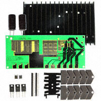
This easy-to-use kit provides a platform for the evaluation of linear power amplifiers circuits using the
PA90/PA91/PA92/PA93/PA98 pin-out. With ample breadboarding area it is flexible enough to analyze a multitude of standard or proprietary circuit configurations. Critical connections for power supply bypassing, compensation and current limiting are pre-wired. Components not usually readily available in engineering labs
are provided. External connections to the evaluation kit can be made via the terminals at the edge of the circuit board. These terminal pads are suitable for standard banana jacks or direct soldering of wires. The schematic is shown in Figure 2.
Figure 1: PCB Layout
TOP SIDE
12
1
IC
C1
C2
+
Rc
IC
-
Cc
GND
C3
EVAL20 R
+
-
2.87
+
OUTPUT
DRIVE
C4
COMPONENT & DUT SIDE
R LIM
M I C R O T E C H N O L O G Y
SPARE
SPARE
SPARE
-IN
+IN
-Vs
GND
+Vs
OUTPUT
DRIVE
GND
6.68
BOTTOM SIDE
EVAL20
APEX
CIRCUIT SIDE
www.apexanalog.com
GND
1
© Apex Microtechnology Inc.
All rights reserved
12
Sep 2020
EK16U Rev J
�EK16
Figure 2: EK Schematic
Figure 2 shows the schematic of the evaluation kit's pre-wired connections. Components supplied with
the kit are marked with an asterisk (*). All other connections are made via the bread-boarding areas of the
circuit board.
2
EK16U Rev J
�EK16
Figure 3: Test Circuit
Figure 3 shows a suggested simple test circuit that you can build to gain a familiarity with the evaluation
kit as well as the amplifier. At the output (pin 6) you should observe a 100 V p-p sine wave.
EK16U Rev J
3
�EK16
PARTS LIST
Reference
Manufacturer Part #
Description
HS23
HS20
310-43-120-41-001000
EVAL20
TW07
ZX7R105KTL
EC02
Heatsink
Heatsink
Mating Socket Strip
PC Board
Thermal Washer
Capacitor, 1µF, ceramic
Capacitor, 33µF electrolytic
MP930 - 0.30 - 1%
Resistor, 0.3 Ω
1
RLIM
MP930 - 0.20 - 1%
Resistor, 0.2 Ω
1
RLIM
MP930 - 0.10 - 1%
Resistor, 0.1 Ω
1
C1, C2
C3, C4
RLIM
QTY
1
1
1 bag (2 each)
1
1 box (10 each)
2
2
ASSEMBLY
1. See Figure 1. Solder the surface mount ceramic capacitors to the DUT side of the circuit board at C1 and
C2.
2. Solder the electrolytic capacitors to the circuit board at C3 and C4. Match the polarity markings on the
circuit board with those on the capacitor body.
3. Select a current limiting resistor from the three values provided. See the product data sheet for information on how to select a value. Apply a thin coating of thermal grease to the back of the resistor. Using a 440 X 1/4” screw and 4-40 nut, mount the resistor to the lower of the two holes in the small heat sink provided. Solder this assembly to the circuit board at RLIM. After soldering the resistor leads the tabs on the
heat sink may be bent with pliers to secure it to the circuit board.
4. Examine the large heat sink. Notice that there are several holes in the face of the heat sink. These are for
mounting various Apex Microtechnology amplifier models. The circuit board aligns the amplifier with the
correct mounting hole once the heat sink is attached to the circuit board. The heat sink can be mounted
in either of two positions. One position is used for mounting the amplifier to the heat sink without the
mating socket strip (the mounting hole of the amplifier is closer to the circuit board). Rotating the heat
sink 180 degrees allows mounting the amplifier with the mating socket strip (the mounting hole of the
amplifier is further from the circuit board).
5. While developing your application circuit you will probably want to use the mating socket strip. Clip off
the strip after the 12th position. Insert the strip into the circuit board from the DUT side and solder one
pin on the reverse side. Check that the mating socket strip is fully seated against the circuit board then
solder the remaining pins. Insert the amplifier fully into the mating socket strip, noting the pin 1 locations
on the amplifier and the circuit board.
6. The four holes at the corners of the circuit board are for mounting #6 standoff spacers if desired. The
remaining two slotted holes are for mounting the large heat sink to the DUT side of the circuit board.
Temporarily mount the heat sink with 2 #6 X 1/2” self tapping screws from the opposite side of the circuit
board. Do not fully tighten the screws at this time. Check for alignment of the slot in the mounting tab of
the amplifier with a hole in the heat sink. Dismount and rotate the heat sink if necessary to achieve an
alignment with a hole in the heat sink. Position the heat sink so that the back of the amplifier mounting
tab is flush with the heat sink then tighten the heat sink mounting screws.
7. Hang the thermal washer near the end of a 6-32 X 1/2” screw. Slightly pull the amplifier away from the
heat sink face. Use the screw to position the thermal washer behind the amplifier and insert the screw
4
EK16U Rev J
�EK16
into the mounting hole of the heat sink. Secure the screw from the opposite side of the heat sink using a
nut holder.
8. Add other components as necessary to complete your application circuit.
Figure 4: Mechanical Drawing
NEED TECHNICAL HELP? CONTACT APEX SUPPORT!
For all Apex Microtechnology product questions and inquiries, call toll free 800-546-2739 in North America. For
inquiries via email, please contact apex.support@apexanalog.com. International customers can also request
support by contacting their local Apex Microtechnology Sales Representative. To find the one nearest to you,
go to www.apexanalog.com
IMPORTANT NOTICE
Apex Microtechnology, Inc. has made every effort to insure the accuracy of the content contained in this document. However, the information is
subject to change without notice and is provided "AS IS" without warranty of any kind (expressed or implied). Apex Microtechnology reserves the right
to make changes without further notice to any specifications or products mentioned herein to improve reliability. This document is the property of
Apex Microtechnology and by furnishing this information, Apex Microtechnology grants no license, expressed or implied under any patents, mask
work rights, copyrights, trademarks, trade secrets or other intellectual property rights. Apex Microtechnology owns the copyrights associated with the
information contained herein and gives consent for copies to be made of the information only for use within your organization with respect to Apex
Microtechnology integrated circuits or other products of Apex Microtechnology. This consent does not extend to other copying such as copying for
general distribution, advertising or promotional purposes, or for creating any work for resale.
APEX MICROTECHNOLOGY PRODUCTS ARE NOT DESIGNED, AUTHORIZED OR WARRANTED TO BE SUITABLE FOR USE IN PRODUCTS USED FOR LIFE
SUPPORT, AUTOMOTIVE SAFETY, SECURITY DEVICES, OR OTHER CRITICAL APPLICATIONS. PRODUCTS IN SUCH APPLICATIONS ARE UNDERSTOOD TO BE
FULLY AT THE CUSTOMER OR THE CUSTOMER’S RISK.
Apex Microtechnology, Apex and Apex Precision Power are trademarks of Apex Microtechnology, Inc. All other corporate names noted herein may be
trademarks of their respective holders.
EK16U Rev J
5
�
很抱歉,暂时无法提供与“EK16”相匹配的价格&库存,您可以联系我们找货
免费人工找货