物料型号:4448R 4448,这是一款表面贴装高电流功率电感器。
器件简介:该电感器采用粉末铁芯或铁合金芯,具有高电流承载能力,适用于功率转换应用。
引脚分配:电感器有两个内部电感器,内部引脚分配为:#1(起始)- #2(结束)和#4(起始)- #3(结束)。外部连接方式有两种:串联和并联。串联时,#2连接到#4;并联时,#1连接到#4,#2连接到#3。
参数特性:电感值、直流电阻、额定直流电流、最大直流电流、电感公差等参数随不同型号而变化。例如,-02M型号的电感值为0.47μH,公差为±20%,额定直流电流为7.90A,最大直流电阻为0.020欧姆。
功能详解:电感器在电路中起到滤波、储能、抑制噪声等作用,有助于提高电源转换效率和稳定性。
应用信息:适用于高电流功率转换,如开关电源、电池充电器、LED照明等。
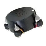
封装信息:电感器具有平坦的顶部表面贴装封装,具有优秀的端子共面性。封装尺寸和重量等物理参数也在文档中给出。