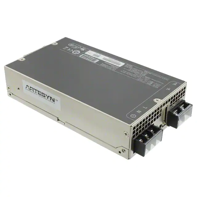
ARTESYN LCM300
300 Watts Bulk Front End
Advanced Energy’s Artesyn LCM300 series provide for a very
AT A GLANCE
wide range of AC-DC embedded power requirement. Featuring
high build quality with robust screw terminals, long life, and
typical full-load efficiency of greater than 91 percent, these units
Total Power
are ideal for use in industrial and medical applications. They are
300 W
backed by a comprehensive set of industrial and medical safety
Input Voltage
approvals and certificates. Variable-speed ‘Smart Fans’ draw
85 to 264 VAC
on software controls developed by Advanced Energy to match
fan speed to the unit’s cooling requirement and load current.
Slowing the fan not only saves power but also reduces wear,
# of Outputs
Single
thus extending its life.
SPECIAL FEATURES
310 W output power (350 W at 45°C
for 24 V and 36 V models)
Low cost
1.61” x 4.0” x 7.0”
7.1 W/in3
Industrial/Medical safety
-40°C to 70°C with derating
Optional 5 V @ 2 A housekeeping
High efficiency: 91% @ 230 VAC
Variable speed “Smart Fans”
DSP controlled
Conformal coat option
Wide adjustment range
Margin programming
OR-ing FET
PMBus compliant
Compliance
EMI Class B
EN61000 Immunity
RoHS 3
PMBus
SAFETY
UL62368-1 508/1598/1433
60601-1 Ed 3
CSA
62368-1
TUV
62368-1
60601-1
China CCC
CB Scheme Report/Cert
CE and UKCA Mark
* Note: LCM300 tested according to the medical standard IEC
60601-1-2 4th Edition.
©2022 Advanced Energy Industries, Inc.
�LCM300
ELECTRICAL SPECIFICATIONS
Input
Input range
90 to 264 VAC (Operating)
115/230 VAC (Nominal)
TERMINAL BLOCK
Frequency
47 to 63 Hz, Nominal 50/60
Input fusing
Internal 8 A fuses, both lines fused
Inrush current
≤ 20 A peak, cold start at 25°C
Power factor
0.98 typical, meets EN61000-3-2
Harmonics
Meets IEC61000-3-2 requirements
Input current
5 Arms max input current, at 90 VAC
Hold up time
20 ms minimum for main O/P, at full rated load
Efficiency
> 91% typical at full load / 230 VAC nominal
Leakage current
< 0.3 mA at 240 VAC
ON/OFF power switch
N/A
Power line transient
MOV directly after the fuse
Isolation
Isolation: PRI-Chassis 2500 VDC Basic
PRI-SEC 4000 VAC Reinforced 2xMOPP
SEC-Chassis 500 VDC
LCM300Q Efficiency Without the 5 Vsb
92.00
90.00
88.00
Efficiency %
86.00
100 Vac
230 Vac
84.00
82.00
80.00
78.00
76.00
25
50
75
Loading %
2 advancedenergy.com
100
�LCM300
ELECTRICAL SPECIFICATIONS (CONTINUED)
Output
Output rating
See table 1
90 to 264 VAC
Set point
± 0.5%
90 to 264 VAC
Total regulation range
Main output ± 2%
5V VSB ± 1%
Combined line/load/transient when measured
at output terminal
Rated load
310 W (360 W for current Q and U variants)
Derate linear to 50% from 50°C to 70°C
Minimum load
Main output @ 0.0 A
5V VSB @ 0.0 A
No loss of regulation
Output noise (PARD)
1% max p-p
100 mV max p-p
Main output
5V VSB output
Measured with a 0.1 μF Ceramic and 10 μF
Tantalum Capacitor on any output, 20 MHz
Output voltage overshoot
Transient response
No overshoot/undershoot outside the regulation
band during on or off cycle
< 300 µSec
Max units in parallel
Short circuit protection
50% load step @ 1 A/µs
Step load valid between 10% to 100% of output
rating
Recovery time to within 1% of set point at onset
of transient
Up to 10
Protected, no damage to occur
Remote sense
Bounce mode
Compensation up to 500 mV
Output isolation
Standard per safety requirements
Forced load sharing
To within 10% of all shared outputs
Analog sharing control
Overload protection (OCP)
105% to 125%
120% to 170%
Main output
5V VSB output
Overvoltage protection (OVP)
125% to 145%
110% to 125%
12 V output
5V VSB output
ENVIRONMENTAL SPECIFICATIONS
Operating temperature
-40°C to +70°C, linear derating to 50% from 50°C to 70°C
Storage temperature
-40°C to +85°C
Humidity
10 to 90%, non-condensing. Operating. Conformal coat option available
Fan noise
< 45 dBA, 80% load at 40°C; Fan Off when unit is inhibited
Altitude
Operating - 16,405 feet (5000 m)
Storage - 30,000 feet
Shock
MIL-STD-810F 516.5, Procedure I, VI. Storage
Vibration
MIL-STD-810F 514.5, Cat. 4, 10. Storage
advancedenergy.com
3
�LCM300
ORDERING INFORMATION
Model
Number*
Output
Nominal
Output
Voltage Set
Point
Set Point
Tolerance
Adjustment
Range
Max
Output
Ripple
P/P (0-50 ˚C)
Max
Continuous
Power
Combined
Line/Load
Regulation
Current
Min
LCM300L
12 V
12 V
± 0.5%
9.6 - 14.4 V
0A
25.0 A
120 mV
310 W
2%
LCM300N
15 V
15 V
± 0.5%
14.25 - 19.5 V
0A
20.0 A
150 mV
310 W
2%
LCM300Q
24 V
24 V
± 0.5%
19.2 - 28.8 V
0A
12.5 A
240 mV
310 W
2%
LCM300U
36 V
36 V
± 0.5%
28.8 - 43.2 V
0A
8.4 A
360 mV
310 W
2%
LCM300W
48 V
48 V
± 0.5%
43.0 - 60.0 V
0A
6.3 A
480 mV
310 W
2%
*Note: 14.5 A rating on LCM300Q-T and 9.7 A on LCM300U-T when max temp does not exceed 45°C (Total Power = 350 W)
LCMXXXXY
-
Case Size
A
-
Input Termination
B
-
C
-
###
Acoustic Noise
Option Codes
Hardware Code
Blank = Standard
Blank = No Options
Factory Assigned for
Modiefied Standards
1-Phase input where XXXX =
300 = 1.61” x 4.0” x 7.0”, 300 W
T = Terminal Block
1 = Conformal Coat
Voltage Code Y =
4 = 5 V Standby
Code
5 = Opt 1 + 4
L
12
N
15
Q
24
U
36
W
48
PN 602-000180-0000
SCR-PP MC M4X0.7
W/E-T-W
11,6
INPUT TERMINAL BLOCK
LED (AC OK)
LED (DC OK/FAIL)
SK2 SIGNAL CONNECTOR-20WAY
LED INDICATORS
POS SK4
NEG SK5
Signal Output Signal Connectors (SK2)
SK2 Mating Connector: JST Part Number PHDR-20VS;
Contact Pins: JST Part Number SPHD-001T-P0.5
2 provided are clearly visible up to a 45 degree offset from vertical with office environment ambient lighting. The status is reflected in the indicator color.
The DC_OK LED LED shall light green if the DC output is within specification, and should be off if the output falls out of specification.
The AC_OK LED LED is green if the AC is within specification and off when out of specification. Note: With 5 V standby, Green also indicates that
PSU is in standby mode/output off.
CONTROL SIGNALS
AC_OK Open collector 0.5 V maximum at 10 mA. Both emitter and collector access provided.
DC_OK Open collector 0.5 V maximum at 10 mA. Both emitter and collector access provided.
DC_OK will de-assert when output is loss due to OCP, OVP, OTP, or Fan Fault (for -N option).
PS_INHIBIT/ENABLE Signal
4 advancedenergy.com
0.0 to 0.5 V contact closure, output OFF (output ON for LCM300U-T-4-401).
�LCM300
PIN ASSIGNMENT
Signals
+Vout
Name Description
Pin Number(s)
Power rail
GND
SK4
Power GND
Signals
SK5
Name Description
Amps per pin
Pin Number(s)
A2
EEPROM address
1
-VPROG
Return connection of external supply for Margin Programming
2
A1
EEPROM address
3
-Vsense
Remote sense return
4
ISHARE
Load share voltage
5
A0
EEPROM address
6
SDA1
Serial data signal (I2C)
7
+VPROG
Positive connection of external supply for Margin Programming
8
SCL1
Serial clock signal (I2C)
9
+Vsense
Remote sense positive
5VSB
5V standby
2A
11
GND
5V standby return
2A
12
5VSB
5V standby
N/A
13
G_DCOK_C
Global DCOK collector
14
GPIOA6
EEPROM write protect
15
G_DCOK_E
Global DCOK emitter (GND)
16
GND
Return ground for output signal and I2C communication
17
G_ACOK_C
Global ACOK collector
18
INH_EN
Turn Off main output
19
G_ACOK_E
Global ACOK emitter (GND)
20
10
Note: Mating connector for SK2 is:
LANDWIN: PN 2050S2000 Housing and PN 2053T021V Contact
CIVILUX: PN CI0120SD000 Housing and PN CI01TD21PE0 Contact
advancedenergy.com
5
�LCM300
MECHANICAL DRAWINGS
Weight: 1.76 lbs (0.8 Kg)
177,8 0,5
13,02
PRODUCT LABEL
AIR FLOW DIRECTION
41 0,5
PN 602-000180-0000
SCR-PP MC M4X0.7
W/E-T-W
11,6
INPUT TERMINAL BLOCK
101,6 0,5
9,5
RECOMMENDED SCREW TORQUE:
M3 x 0.5P = 6.4 - 8kgf-cm
M3.5 x 0.6P = 6 - 8kgf-cm
M4.0 x 0.7P = 8 - 10kgf-cm
12,85
MOUNTING LOCATIONS SCREW
PENETRATION DEPTH IS 3.0 mm MAX.
9,5
13,66
11,15 REF
POS SK4
NEG SK5
(2X) 9 0,5
LED (DC OK/FAIL)
SK2 SIGNAL CONNECTOR-20WAY
148,7 0,5
(2X) 19 0,5
LED (AC OK)
(2X) 29,1 0,5
(2X) 119,6 0,5
Airflow direction
6 advancedenergy.com
19,05 0,5
63,5 0,5
S-M3-OZ1 (8 PLACES)
�LCM300
ACCESSORIES
PIN 20
PIN 19
PIN 2
PIN 3
PIN 1
300 ± 5 mm
Order kit part number 73-788-001 for control connector interface with 0.3 m wires attached attached
PIN 20
PIN 19
PIN 2
PIN 3
PIN 1
Order kit part number 73-788-002 for control connector interface with unloaded housing and 20 pins
MISCELLANEOUS SPECIFICATIONS
Burn-In
100% Burn-in at 45°C, at 80 to 90% load. Duration of burn-in determined by Quality Assurance Procedures.
MTBF
The power supply has a minimum MTBF of 300K hours using the Bell core 332, issue 6 specification @ 25°C and 40°C, ambient, at full load. With
the power supply installed in a system in a 25°C ambient environment and operating at full load, capacitor life shall be 5 years at 50°C, minimum
for ALL electrolytic capacitors contained within this power supply. The power supply shall demonstrate a MTBF level of > 500,000 hours.
Quality Assurance
Full QAV testing shall be conducted in accordance with Advanced Energy Standards.
Warranty
Advanced Energy shall warrant the power supply to be free of defects in materials and workmanship for a minimum period of three years from
the date of shipment, when operated within specifications. The warranty shall be fully transferable to the end owner of the equipment powered
by the supply.
advancedenergy.com
7
�ABOUT ADVANCED ENERGY
Advanced Energy (AE) has devoted more than three
decades to perfecting power for its global customers. AE
designs and manufactures highly engineered, precision
power conversion, measurement and control solutions for
mission-critical applications and processes.
Our products enable customer innovation in complex
applications for a wide range of industries including
semiconductor equipment, industrial, manufacturing,
telecommunications, data center computing, and medical.
With deep applications know-how and responsive service
and support across the globe, we build collaborative
partnerships to meet rapid technological developments,
propel growth for our customers, and innovate the future
of power.
For international contact information,
visit advancedenergy.com.
powersales@aei.com (Sales Support)
productsupport.ep@aei.com (Technical Support)
+1 888 412 7832
Specifications are subject to change without notice. Not responsible
for errors or omissions. ©2022 Advanced Energy Industries, Inc. All rights
reserved. Advanced Energy®, AE® and Artesyn™ are U.S. trademarks
of Advanced Energy Industries, Inc.
ENG-LCM300-235-02 07.29.22
�