Technical Reference Note
Embedded Power for
Business-Critical Continuity
SXX06E
Rev. 08.01.06
Page 1 of 2
Rev. 04.25.11
SIL/SMT80C2
1 of 20
SIL/SMT80C2
80 Amp
Total Power: 400 W
Input Voltage: 4.7 - 13.8 VDC
# of Outputs: Single
Special Features
• 80 A current rating
• Input voltage range:
4.7-13.8 V
• Output voltage: 0.8375-5.1 V
• Current sharing
• Industry leading value
• Cost optimized design
• Excellent transient response
• Output voltage adjustability
• Pathway for future upgrades
• Supports silicon voltage
migration
• Reduced design-in and
qualification time
• Over-temperature protection
• RoHS compliant
Safety
Designed to meet:
• UL, cUL 60950-1
• (EN60950)
Product Family:
Function:
Usage:
SIL/SMT80C2 Series
Single In-Line Power
LEDs, ASIC, Memory, FPGAs, Telecom and
Networking Equipment, Servers,
Industrial Equipment, POL Regulation
Definition:
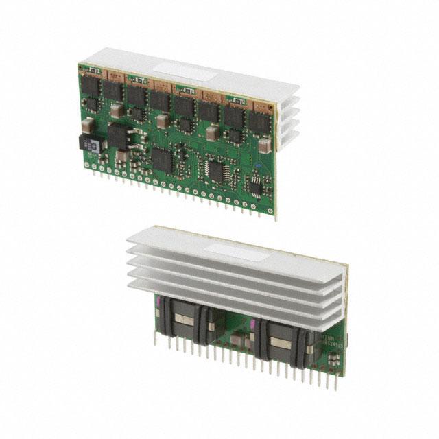
The SIL/SMT80C2 is a new high density open frame non-isolated
converter series for space-sensitive applications. Each model has
a wide input voltage range (4.7 - 13.8 V) and offers a wide 0.8375
- 5.1 V output voltage range with a 80 A load. An external resistor
adjusts the output voltage from its pre-set value of 0.8375 V to
any value up to the maximum allowed value for that model. The
SIL/SMT80C2 offers remote ON/OFF and over-current protection
as standard.
�Technical Reference Note
Embedded Power for
Business-Critical Continuity
Rev. 04.25.11
SIL/SMT80C2
2 of 20
General Description
Electrical Description
The SIL/SMT80C2 is implemented using a multi-phase synchronous buck topology. A block diagram of
the converter is shown in Figure 1.
The output is adjustable over a range of
0.8375-5.1 V by using a resistor from the trim pin
to -trim pin, or by driving the TRIM pin with a
voltage.
SIL80C2
Vin
Vout
Phase 1
Upper G/Drive
Tri
m
Ilimit
PWRGD
The converter can be shut down via the enable
pin. This input is run with positive logic that is
compatible with popular logic devices. Positive
logic implies that the converter is enabled if the
input is high (or floating), and disabled if it is low.
L out1
∩∩∩
V out
Lower G/Drive
Remote
ON/OFF
GND
Phase 2
L out2
Upper G/Drive
∩∩∩
Lower G/Drive
Phase 3
L out3
Upper G/Drive
∩∩∩
Lower G/Drive
Phase 4
Output is monitored for overcurrent and shortcircuit conditions. When the PWM controller
detects an overcurrent condition, it forces the
module into hiccup mode.
L out4
Upper G/Drive
∩∩∩
Lower G/Drive
Figure 1 - Electrical Block Diagram
A typical application is shown in Figure 2.
Wide Operating Temperature Range
The SIL/SMT80C2's ability to accommodate a wide
range of ambient temperatures is the result of its
extremely high power conversion efficiency and
resultant low power dissipation, combined with the
excellent thermal performance of the PCB substrate.
Maximum output power that the module can deliver
depends on a number of parameters, primarily:
Ishare
Enable On/Off
Power Good
4
Vout
15,16,18,
20,22,24
11
+Sense
SIL80C2
6
9
R uvlo
Vin
12-14
3,7,8,17,
19,21,23 1
C in
GND
5
R trim
10
C out
R
L
O
A
D
-Sense GND
•
•
•
•
Input voltage range
Output load current
Figure 2 - Standard Application Drawing
Air velocity (forced or natural convection)
Mounting orientation of target application PCB, i.e., vertical/horizontal mount, or mechanically tied
down (especially important in natural convection conditions).
• Target application PCB design, especially ground planes. These can be effective heatsinks for the converter.
The SIL/SMT80C2 module has an operating temperature range of 0 °C to 85 °C with suitable derating and/
or forced air cooling.
�Technical Reference Note
Embedded Power for
Business-Critical Continuity
Rev. 04.25.11
SIL/SMT80C2
3 of 20
Features and Functions
Output Voltage Adjustment
The output voltage on all models is adjustable from 0.8375-5.1 V.
Undervoltage Lockout
The default undervoltage lockout is set at 4.7 V.
Current Limit and Short-Circuit Protection
The SIL/SMT80C2 model has a built-in non-latching current limit function and continuous short-circuit
protection. When an overcurrent condition occurs, the module goes into hiccup mode, where it attempts
to power up periodically to determine if the problem persists.
Note that none of the module specifications are guaranteed when the unit is operated in an overcurrent
condition.
Enable
The enable pin allows external circuitry to put the SIL/SMT80C2 converter into a low dissipation standby
mode. Positive logic enable pin is available as standard.
The unit is turned on if the enable pin is high (or floating). Pulling the pin low will disable the unit. To
guarantee turn-on, the enable voltage must be above 1.25 V. To disable, the enable voltage must be
pulled below 0.7 V.
Figures 3 and 4 show various circuits for driving the Enable feature. The Enable input can be driven
through a discrete device (i.e. a bipolar signal transistor) or directly from a logic gate output. The output
of the logic gate may be an open-collector (or open-drain) device.
SIL80C2
Vin
Vout
Enable
Tri
m
Ground
Figure 3 - Enable Input Drive Circuit for Non-Isolated Biopolar
5 V
SIL80C2
Vin
Vout
Enable
Tri
m
Ground
Figure 4 - Enable Input Drive Circuit for Logic Driver
�Technical Reference Note
Embedded Power for
Business-Critical Continuity
Rev. 04.25.11
SIL/SMT80C2
4 of 20
Features and Functions
Power Good
The SIL/SMT80C2 modules have a power good indicator output. This output pin uses positive logic and is
open collector. Also, the power good output is able to sink 1 mA. The power good signal should not be
pulled any higher than 5.1 V.
When the output of the module is within ±10% of the nominal set point, the power good pin can be pulled
high.
Overtemperature Protection (OTP)
The SIL/SMT80C2 is equipped with non-latching overtemperature protection. A temperature sensor
monitors the temperature of the PCB near one the main FETs. If the temperature exceeds a threshold of
150 °C (typical) the converter will shut down, disabling the output. When the substrate temperature has
decreased by 10 °C the converter will automatically restart.
The converter might experience overtemperature conditions during a persistent overload on the output.
Overload conditions can be caused by external faults. OTP might also be entered due to a loss of control
of the environmental conditions (e.g. an increase in the converter’s ambient temperature due to a failing
fan).
�Technical Reference Note
Embedded Power for
Business-Critical Continuity
Rev. 04.25.11
SIL/SMT80C2
5 of 20
Application
Output Voltage Adjustment
The output of the module can be adjusted, or trimmed, from 0.8375 V to 5.1 V. This is accomplished by
connecting an external resistor between the Trim pin and -Trim as shown in Figure 5 or with a voltage as
shown in Figure 6. Extremely high accuracy setpoints can be achieved with the use of a potentiometer as
shown in Figure 7.
SIL80C2
SIL80C2
Vout
Vout
Vin
Vin
Rtrim2
Tri
m
Tri
m
Enable
Enable
Rtrim
Vt
Rtrim1
-Trim
-Trim
Figure 5 - Output Voltage Trim
Figure 6 - Output Votlage Trim - with Voltage Source
Vout
Vin
Tri
m
Rtrim1
Enable
Rtrim2
Rpot1
-Trim
REQUIRED TRIM RESISTOR (OHM)
1000000
SIL80C2
100000
10000
1000
100
10
1
0
1
2
3
4
DESIRED OUTPUT VOLTAGE SETPOINT (V)
Figure 7 - Output Voltage - with Potentiometer
Figure 8 - Typical Trim Curves
5
�Technical Reference Note
Embedded Power for
Business-Critical Continuity
Rev. 04.25.11
SIL/SMT80C2
6 of 20
Application (cont'd)
Output Voltage Adjustment (cont'd)
The trim equation for the basic configuration shown in Figure 5 is:
R
1.675
trim(kΩ) =
Vout - 0.8375
Where Vout is the desired output voltage, Rtrim is the resistance required between Trim and
-Trim.
The trim equation for the external voltage configuration shown Figure 6 is:
R
Rtrim1 (1.2 - 2Vt)
trim2(kΩ) =
Rtrim1 (Vout - 0.8375) - 1.675
Where Vout is the desired output voltage, Rtrim1 and Rtrim2 are the resistors in Figure 6
and Vt is the applied external voltage.
The trim equation for the potentiometer configurations shown in Figure 7 is:
0.8375
Vout =
(Rtrim2 + Rpot)Rtrim1
X (2Rtrim2 + 2Rpot + Rtrim1Rtrim2 + Rtrim1Rpot + 2Rtrim1)
Where Vout is the desired output voltage, Rtrim1 and Rtrim2 are the resistors in Figure 7
and Rpot is the resistance of the potentiometer.
Undervoltage Lockout
The SIL/SMT80C2 has built-in undervoltage lockout to ensure reliable output power. The lockout prevents
the unit from operating when the input voltage is too low. The UVLO for the SIL/SMT80C2 can be adjusted with the following equation:
The trim equation for the undervoltage lockout is:
124.8 + Vturn_on
Ruvlo (kΩ) =
10 Vturn_on - 42.06
�Technical Reference Note
Embedded Power for
Business-Critical Continuity
Rev. 04.25.11
SIL/SMT80C2
7 of 20
Application (cont'd)
Remote Sense Compensation
The remote sense compensation feature minimizes the effect of resistance in the distribution system
and facilitates accurate voltage regulation at the load terminals or another selected point. The remote
sense lines will carry very little current and hence do not require a large cross-sectional area. However, if
the sense lines are routed on a PCB, they should be located close to a ground plane in order to minimize
any noise coupled onto the lines that might impair control loop stability. The module will compensate
for a maximum drop of 400 mV. Remember that when using remote sense compensation all the resistance, parasitic inductance and capacitance of the distribution system are incorporated into the feedback
loop of the power module. This can have an effect on the modules compensation capabilities, affecting
its stability and dynamic response.
Parallel Operation
Parallel operation of multiple converters is available since the SIL/SMT80C2 has a current sharing option.
The converter will share to within ±10% of full load. To current share, Pin 6 of each module should be
connected. Also, the remote sense lines should be connected at the same point. Figure 9 shows the
typical current sharing application.
SIL80C2
Vin 12-14
Vout
Tri
m
10 Sense+
-Trim
11 SenseIshare 6
GND
SIL80C2
Vin 12-14
Vout
Tri
m
10 Sense+
-Trim
11 SenseIshare 6
GND
Figure 9 - Parallel Application
R
L
O
A
D
Cload
�Technical Reference Note
Embedded Power for
Business-Critical Continuity
Rev. 04.25.11
SIL/SMT80C2
8 of 20
Application (cont'd)
Output Capacitance
The SIL/SMT80C2 has output capacitors inside the converter. No output capacitance is required for
stable operation. When powering loads with large dynamic current requirements, improved voltage
regulation is obtained by inserting low ESR capacitors as close as possible to the load. Low ESR
ceramic capacitors will handle the short duration high frequency components of the dynamic current
requirement. In addition, higher values of electrolytic capacitors should be used to handle the midfrequency components.
It is equally important to use good design practices when configuring the dc distribution system. Low
resistance and low inductance PCB layout traces should be utilized, particularly in the high current output
section. Remember that the capacitance of the distribution system and the associated ESR are within the
feedback loop of the power capabilities, thus affecting the stability and dynamic response of the module.
Note that the maximum rated value of output capacitance varies between models and for each output
voltage setpoint. A stability vs. Load Capacitance calculator, (see your sales representative), details how
an external load capacitance influences the gain and phase margins of the SIL/SMT80C2.
SMT Reflow Guidelines
For a SnPb process: Pads should be above 183C (liquidus) for 90 seconds max (60-75 seconds typical)
with a peak temperature of 225C. For a leadfree SAC305 process: pads should be above 217C (liquidus)
for 90 seconds max (60-75 seconds typical) with a peak temperature of 250C.
Water Washing
Not recommended.
�Technical Reference Note
Embedded Power for
Business-Critical Continuity
Rev. 04.25.11
SIL/SMT80C2
9 of 20
Parameter
Test Conditions
Min
Typ
Max
Units
Absolute Maximums
Input Voltage
0
13.8
V
Enable Voltage
0
5
V
Operating Ambient Temperature
0
85
˚C
-40
125
˚C
4.7
13.8
Vdc
Non-Operating Ambient Temperature
Input Specifications
Input Voltage
Input Current (No Load)
Vin(min) - Vin(max), enabled
500
mA
Converter disabled
10
mA
Input Capacitance (Internal)
Internal to converter
176
uF
Input Capacitance (External)
Recommend customer added capacitance
47
uF
Input Current (quiescent)
Output Specifications
0.8375
5.0
V
Output Setpoint Accuracy
-1.0
+1.0
%
Output Regulation (Line)
-0.2
+0.2
%
Output Regulation (Load)
-0.5
+0.5
%
0
80
A
130
140
A
Ouput Voltage
Output Current (continuous)
Output Current (short circuit)
0.9, 2.5, 5.1 Vout
Output Capacitance (Internal)
Output Capacitance (External)
500
uF
12 Vin, 0.9 Vout (Startup capacitance)
0
63,000
uF
12 Vin, 2.5 Vout (Startup capacitance)
0
30,000
uF
12 Vin, 5 Vout (Startup capacitance)
0
11,000
uF
20
mV
12 Vin, 2.5 Vout, 0 uF Cout
20
mV
12 Vin, 5 Vout, 0 uF Cout
20
mV
5.1 Vin, 0.9 Vout, 80 Aout
82.2
%
12 Vin, 2.5 Vout, 80 Aout
89.1
%
12 Vin, 5 Vout, 80 Aout
93.3
%
Dynamic Load Response (Peak Deviation)
12 Vin, 0.9 Vout, 50-75% load at 10 A/us
95
mV
Dynamic Load Response (Setting Time)
12 Vin, 0.9 Vout, 50-75% load at 10 A/us
30
us
Dynamic Load Response (Peak Deviation)
12 Vin, 2.5 Vout, 50-75% load at 10 A/us
150
mV
Dynamic Load Response (Setting Time)
12 Vin, 2.5 Vout, 50-75% load at 10 A/us
30
us
Dynamic Load Response (Peak Deviation)
12 Vin, 5 Vout, 50-75% load at 10 A/us
150
mV
Dynamic Load Response (Setting Time)
12 Vin, 5 Vout, 50-75% load at 10 A/us
30
us
Output Ripple/Noise (Peak/Peak)
Efficiency
5 Vin, 0.9 Vout, 0 uF Cout
�Technical Reference Note
Embedded Power for
Business-Critical Continuity
Rev. 04.25.11
SIL/SMT80C2
10 of 20
Parameter
Test Conditions
Min
Typ
Max
Units
2.7
3
ms
3
12
ms
1.8
2
ms
0.7
V
Turn On Specifications
Turn On Delay (with Vin)
Turn On Delay (with Enable)
Output Rise TIme
10% - 90%
Enable Specifications
Signal Low (Unit Off)
0
Signal Low Current
12 Vin
Signal High (Unit On)
12 Vin
1.2
mA
3.4
V
1.0
µA
108
A
Input Under Voltage (Rising)
4.7
V
Input Under Voltage (Falling)
4.0
V
3.7
MHrs
45.36
g
500
kHz
Signal High Current
0
Protection Specifications
Over Current Protection
Hiccup Mode
General Specifications
MTBF
Telcorida SR-332
Weight
Switching Frequency
Per Phase
Coplanarity
TBD
Material Ratings
Flammability
UL94V-0
Material Type
FR4 PCB
�Technical Reference Note
Embedded Power for
Business-Critical Continuity
Rev. 04.25.11
SIL/SMT80C2
11 of 20
0.9 V Setpoint
80
80
70
70
60
60
200 LFM
300 LFM
400 LFM
500 LFM
50
Load Current (A)
200 LFM
300 LFM
400 LFM
500 LFM
600 LFM
40
40
30
30
20
20
10
10
0
0
30
40
50
60
70
80
30
Ambient (C)
40
50
60
70
80
Ambient (C)
Figure 10: Thermal Derating Curve 5.5 Vin
Figure 11: Thermal Derating Curve 12 Vin
Thermal derating - 600LFM minimum airflow
90
80
70
60
Load (A)
Load Current (A)
600 LFM
50
50
4.7Vin,
0.84Vout
13.8Vin,
5.1Vout
13.8Vin,
5.0Vout
40
30
20
10
0
25
30
35
40
45
50
55
60
65
70
75
80
85
Ambient temp (ºC)
Figure 11A: Thermal derating curve 4.7Vin and 13.8Vin
Figure 13: Control On/Off
(Channel 1: Output Voltage, Channel 3: Enable)
Figure 12: Effiiciency 0.9 V
Figure 14: Typical Ripple Output
�Technical Reference Note
Embedded Power for
Business-Critical Continuity
Rev. 04.25.11
SIL/SMT80C2
12 of 20
0.9 V Setpoint
Figure 15: Transient Response 75% - 100%
(Channel 3: Current Step at 10 A/div,
Channel 4: Output Voltage Deviation)
Figure 16: Short Circuit Characteristic
(Channel 1: Output Current at 50 A/div,
Channel 4: Output Voltage)
�Technical Reference Note
Embedded Power for
Business-Critical Continuity
Rev. 04.25.11
SIL/SMT80C2
13 of 20
2.5 V Setpoint
80
80
70
70
60
60
50
200 LFM
300 LFM
400 LFM
500 LFM
600 LFM
40
Load Current (A)
Load Current (A)
50
30
30
20
20
10
10
0
200 LFM
300 LFM
400 LFM
500 LFM
600 LFM
40
0
30
40
50
60
70
Ambient (C)
80
30
40
50
60
70
80
Ambient (C)
Figure 17: Thermal Derating Curve 5.1 Vin
Figure18: Thermal Derating Curve 12 Vin
Figure 19: Efficiency 2.5 V
Figure 20: Control On/Off
(Channel 1: Output Voltage, Channel 3: Enable)
Figure 21: Typical Ripple Output
Figure 22: Transient Response 75% - 100%
(Channel 3: Current Step at 10 A/div,
Channel 4: Output Voltage Deviation)
�Technical Reference Note
Embedded Power for
Business-Critical Continuity
Rev. 04.25.11
SIL/SMT80C2
14 of 20
2.5 V Setpoint
Figure 23: Short Circuit Characteristic
(Channel 1: Output Current at 50 A/div,
Channel 4: Output Voltage)
�Technical Reference Note
Embedded Power for
Business-Critical Continuity
Rev. 04.25.11
SIL/SMT80C2
15 of 20
5.0 V Setpoint
80
70
60
Load Current (A)
50
200 LFM
300 LFM
400 LFM
500 LFM
600 LFM
40
30
20
10
0
30
40
50
60
70
80
Ambient (C)
Figure 24: Thermal Derating Curve 12 Vin
Figure 26: Control On/Off
(Channel 1: Output Voltage, Channel 3: Enable)
Figure 28: Transient Response 75% - 100%
(Channel 3: Current Step at 10 A/div,
Channel 4: Output Voltage Deviation)
Figure 25: Efficiency 5.0 V
Figure 27: Typical Output Ripple - ADD TEST CONDITIONS
Figure 29: Short Circuit Characteristic
(Channel 1: Output Current at 50 A/div,
Channel 4: Output Voltage)
�7
8
6
4
5
Technical Reference Note
3
Embedded Power for
Business-Critical Continuity
PART NUMBER
REV
7091259-0000
A
D
Rev. 04.25.11
SIL/SMT80C2
16 of 20
APPLY LIQUI-BOND BETWEEN HEATSINK
AND PCB. ADJUST APPLICATION STENCIL TO
KEEP EXCESS LIQUI-BOND TO A MINIMUM
Mechanical Drawings
SIL80C-00SADJ-VJ
C
.690 17.53 MAX
2.400 60.96
.040 1.02
REF .110 2.79
2.320 58.93
REF .062 1.57
1.250 31.75
B
1.160 29.46
Pin 1
.140 3.56 TYP
REF .025±.002 0.64±0.05
SQ PINS
.100 2.54 TYP
21 PLACES
.050 1.27
.050 1.27 TYP
(23X)
2.300 58.42
.050 1.27 TYP
MATERIAL
A
-
UNLESS OTHERWISE
DIMENSIONS ARE IN
TOLERANCES:
2 PLACE
3 PLACE
.015
.03
HOLE TOLERANCE:
APPROVALS
FINISH
Footprint
NOTE:
1. 9300161-0000 PACKAGING AND MATERIAL HANDLING PROCEDURE.
2. COSMETIC AND WORKMANSHIP PER 9300152-0000.
3. LABELS SHOWN FOR PLACEMENT REFERENCE ONLY.
4
5
FOOTPRINT
8
6
7
-
THIRD
ANGLE
PROJECTION
DETACHED LIST
3
.730 18.54
Ø 0.45 ±.003
THROUGH HOLE
[1.14
±0.08]
.040"
DIA
(23X)
23x
.242 6.15
.192 4.88
.130 3.30
PCB OUTLINE
2.370 60.20
2.420 61.47
2.440 61.98
2.170 55.12
2.070 52.58
1.970 50.04
1.870 47.50
1.770 44.96
1.670 42.42
1.570 39.88
1.470 37.34
1.370 34.80
1.270 32.26
1.170 29.72
1.070 27.18
.970 24.64
.870 22.10
.770 19.56
.670 17.02
.570 14.48
.370 9.40
.470 11.94
.270 6.86
0 0
.020 0.51
.070 1.78
.170 4.32
ENGINEER
M. HENNIES
7001259-J000
KEEP OUT AREA
0 0
DRAWN
M. HENNIES
�D
Technical Reference Note
C
Embedded Power for
APPLY LIQUI-BOND BETWEEN
HEATSINK
Business-Critical
Continuity
AND PCB. ADJUST APPLICATION STENCIL TO
KEEP EXCESS LIQUI-BOND TO A MINIMUM
Rev. 04.25.11
SIL/SMT80C2
17 of 20
Mechanical Drawings
SIL/SMT80C2-00SADJ-HJ/H3J
.710 MAX 18.03 MAX
2.400 60.96
.040 1.02
B
REF .062 1.57
2.320 58.93
REF .110 2.79
1.250 31.75
2X 1.160 29.46
.050 1.27 TYP
(23X)
REF
3.05
L - .120
See Table
.050 1.27
Pin 1
.100 2.54 TYP
21 PLACES
.125 3.18 TYP
2.300 58.42
A
Model
L Dimension
SIL80C2-00SADJ
REF .120 [3.05]
SIL80C2-00SADJ-H3J
8
7
Footprint8
4
5
6
3
FOOTPRINT
D
-
REF .138 [3.50]
2
NOTE:
1. 9300161-0000 PACKAGING AND MATERIAL HANDLING PROCEDURE.
2. COSMETIC AND WORKMANSHIP PER 9300152-0000.
3. LABELS SHOWN FOR PLACEMENT REFERENCE ONLY.
4
5
6
7
MATERIAL
FINISH
1
7001259-J100
DETACHED LIST
3
KEEP OUT AREA
D
1.290 32.77
1.270 32.26
1.230 31.24
Ø 0.45 ±.003
THROUGH HOLE
[1.14
±0.08]
.040"
DIA
(25X)
25X
C
C
PCB OUTLINE
B
57.66
60.20
61.47
61.98
2.270
2.370
2.420
2.440
2.170 55.12
2.070 52.58
1.970 50.04
1.870 47.50
1.770 44.96
1.670 42.42
1.570 39.88
1.470 37.34
1.370 34.80
1.270 32.26
1.170 29.72
.970 24.64
.870 22.10
.770 19.56
.670 17.02
.570 14.48
.370 9.40
.470 11.94
1.070 27.18
A
.270 6.86
.070 1.78
.020 0.51
0 0
0 0
.020 0.51
.070 1.78
B
A
DWG. NO.
TITLE:
7091259-0100
REV.
A
�7
8
6
4
5
1
2
3
REVISION RECORD
Technical Reference Note
Embedded Power for
7091259-0300
A
RELEASE TO PRODUCTION
Business-Critical Continuity
PART NUMBER
REV
DESCRIPTION
DRAFT
DATE
M. HENNIES
03/06/07
D
Rev. 04.25.11
SIL/SMT80C2
18 of 20
APPLY LIQUI-BOND BETWEEN HEATSINK
AND PCB. ADJUST APPLICATION STENCIL TO
KEEP EXCESS LIQUI-BOND TO A MINIMUM
Mechanical Drawings
SMT80C-00SADJ-VJ
C
REF .062 1.57
2.400 60.96
DETAIL A
.677 17.20
.040 1.02
REF .110 2.79
.040 1.02 TYP
(2X)
B
1.315 33.40
.065 1.65
.280 7.11
.050 1.27 TYP
(23X)
.100 2.54 TYP
21 PLACES
.050 1.27
NOTE: OUTSIDE SUPPORT IS HIDDEN
TO SHOW PIN DIMENSIONS.
A
Pin 1
2.300 58.42
.610 15.49 REF
2.480 62.99
A
UNLESS OTHERWISE SPECIFIED
DIMENSIONS ARE IN INCHES
TOLERANCES:
2 PLACE
3 PLACE
ANGLES
1
.015
.03
MATERIAL
-
HOLE TOLERANCE:
.005
DATE
APPROVALS
FINISH
22JUN06
ENGINEER
M. HENNIES
7001259-J300
8
D
8
7 7
4
55
66
3
SIZE
22JUN06
2
3
A
UPPERCUT 80
SCALE: 3 = 2
2
REV.
7091259-0300
PROJECT USED ON:
B
THIRD
ANGLE
PROJECTION
DETACHED LIST
4
TLA DRAWING
DWG. NO.
DRAWN
M. HENNIES
-
ARTESYN TECHNOLOGIES
EDEN PRAIRIE, MN 55433
PH. 952-941-1100
TITLE:
SHEET 1 OF 2
CAD FILE:
1
1
FOOTPRINT
Footprint
D
VERT SMT STAND OUTLINE
SMT PAD
.300X.040" (23X)
KEEP OUT AREA
.752 19.10
C
C
.670 17.02
.445 11.30
.440 11.18
PCB OUTLINE
5.51
3.94
3.56
3.43
1.02
B
2.620 66.55
61.47
61.98
63.75
65.02
2.420
2.440
2.510
2.560
2.240 56.90
2.140 54.36
2.040 51.82
1.940 49.28
1.840 46.74
1.740 44.20
1.640 41.66
1.540 39.12
1.440 36.58
1.340 34.04
1.240 31.50
1.140 28.96
1.040 26.42
.940 23.88
.840 21.34
.740 18.80
.640 16.26
.540 13.72
.440 11.18
.060
.110
.140
.200
.240
.340
1.52
2.79
3.56
5.08
6.10
8.64
0 0
0 0
B
.217
.155
.140
.135
.040
A
A
DWG. NO.
SIZE
B
TITLE:
7091259-0300
FOOTPRINT
REV.
A
�D
Technical Reference Note
Embedded Power for
Business-Critical
APPLY LIQUI-BOND BETWEEN
HEATSINK Continuity
AND PCB. ADJUST APPLICATION STENCIL TO
KEEP EXCESS LIQUI-BOND TO A MINIMUM
Rev. 04.25.11
SIL/SMT80C2
19 of 20
Mechanical Drawings (cont'd)
C
SMT80C2-00SADJ-J
2.400 60.96
.040 1.02
B
REF .062 1.57
2.320 58.93
REF .110 2.79
1.250 31.75
.040 1.02 TYP
(2X)
2X 1.160 29.46
.050 1.27 TYP
(23X)
.050 1.27
.125 3.18
Pin 1
.100 2.54 TYP
21 PLACES
NOTE:
1. 93
2. CO
3. LA
.710[18.03] MAX
2.300 58.42
A
MATERIAL
-
FINISH
8
7
Footprint
4
5
6
3
2
1
7001259-J200
DETACHED LIST
8
FOOTPRINT
D
4
5
6
7
3
D
KEEP OUT AREA
1.290 32.77
1.270 32.26
1.195 30.35
PCB OUTLINE
C
C
SMT PAD
.045X.070" (25X)
B
B
2.348 59.63
2.420 61.47
2.440 61.98
2.248 57.09
2.148 54.55
2.048 52.01
1.948 49.47
1.848 46.93
1.748 44.39
1.648 41.85
1.548 39.31
1.448 36.77
1.348 34.23
1.248 31.69
1.148 29.15
.948 24.07
1.048 26.61
.848 21.53
.748 18.99
.648 16.45
.548 13.91
.448 11.37
.348 8.83
.248 6.29
A
0 0
.020 0.51
.048 1.21
.040 1.02
.020 0.51
0 0
A
DWG. NO.
SIZE
B
TITLE:
7091259-0200
REV.
A
FOOTPRINT
SHEET 2 OF 2
�Technical Reference Note
Embedded Power for
Business-Critical Continuity
Americas
Pin Chart
Pin Assignments
Pin Assignments
Single Output
1
Trim
2
No Pin
3
Ground
4
Power Good
5
(-) Trim
6
Ishare
7
Ground
8
Ground
9
Enable
10
Rem Sense (-)
11
Rem Sense (+)
12
Vin
13
Vin
Single Output
14
Vin
15
Vout
16
Vout
17
Ground
18
Vout
19
Ground
20
Vout
21
Ground
22
Vout
23
Ground
24
Vout
25
*Mech Support
26
*Mech Support
5810 Van Allen Way
Carlsbad, CA 92008
USA
Telephone: +1 760 930 4600
Facsimile: +1 760 930 0698
Rev. 04.25.11
SIL/SMT80C2
20 of 20
Europe (UK)
Waterfront Business Park
Merry Hill, Dudley
West Midlands, DY5 1LX
United Kingdom
Telephone: +44 (0) 1384 842 211
Facsimile: +44 (0) 1384 843 355
Asia (HK)
14/F, Lu Plaza
2 Wing Yip Street
Kwun Tong, Kowloon
Hong Kong
Telephone: +852 2176 3333
Facsimile: +852 2176 3888
*Horizontal version only
For global contact, visit:
www.PowerConversion.com
techsupport.embeddedpower
@emerson.com
Ordering Information
Product Family
SIL
Product Family
SIL = Single In Line
Product Family
SMT
Product Family
SMT = Surface
Mount
Rated Output
Current
80
Rated
Output
Current
80 = 80 A
Rated Output
Current
80
Rated
Output
Current
80 = 80 A
Performance
Generation
C
Performance
C = Cost
Optimized
Performance
2
-
Generation
2 = Increased
Current
Density
Generation
C
Performance
C = Cost
Optimized
Input Voltage
2
Generation
2 = Increased
Current
Density
00
SADJ
Input Voltage
00 = 4.7-13.8 V
Output Voltage
Single
Adjustable
Output
Input Voltage
-
Output Voltage
Mounting
Option
-
Output Voltage
00
SADJ
Input Voltage
00 = 4.7-13.8 V
Output Voltage
Single
Adjustable
Output
RoHs Compliance(9)
X
X
Mounting
Option
Blank = Horizontal
V = Vertical
Custom
Options
Blank = 3.05 mm pin
3 = 3.50 mm pin
RoHS Compliance
J = Pb-free
(RoHS 6/6 compliant)
Custom
Options
RoHs Compliance(9)
Mounting
Option
-
Custom
Options
J
X
X
J
Mounting
Option
Blank = Horizontal
V = Vertical
Custom
Options
Blank = 3.05 mm pin
3 = 3.50 mm pin
RoHS Compliance
J = Pb-free
(RoHS 6/6 compliant)
While every precaution has been taken to ensure
accuracy and completeness in this literature, Emerson
Network Power assumes no responsibility, and disclaims
all liability for damages resulting from use of this
information or for any errors or omissions.
Emerson Network Power.
The global leader in enabling
business-critical continuity.
AC Power
Connectivity
DC Power
Embedded Computing
Embedded Power
Monitoring
Outside Plant
Power Switching & Controls
Precision Cooling
Racks & Integrated Cabinets
Services
Surge Protection
This is a preliminary datasheet. Emerson
Network Power reserves the right to make
changes to the information contained herein
without notice and assumes no liability as a
result of its use or application.
EmersonNetworkPower.com
Emerson Network Power and the Emerson
Network Power logo are trademarks and service marks of Emerson Electric Co. ©2011
Emerson Electric Co.
�