Features
• High Performance, Low Power AVR® 8-Bit Microcontroller • Advanced RISC Architecture
– 54 Powerful Instructions – Most Single Clock Cycle Execution – 16 x 8 General Purpose Working Registers – Fully Static Operation – Up to 12 MIPS Throughput at 12 MHz Non-volatile Program and Data Memories – 512/1024 Bytes of In-System Programmable Flash Program Memory – 32 Bytes Internal SRAM – Flash Write/Erase Cycles: 10,000 – Data Retention: 20 Years at 85oC / 100 Years at 25oC Peripheral Features – One 16-bit Timer/Counter with Prescaler and Two PWM Channels – Programmable Watchdog Timer with Separate On-chip Oscillator – 4-channel, 8-bit Analog to Digital Converter (1) – On-chip Analog Comparator Special Microcontroller Features – In-System Programmable (2) – External and Internal Interrupt Sources – Low Power Idle, ADC Noise Reduction, and Power-down Modes – Enhanced Power-on Reset Circuit – Programmable Supply Voltage Level Monitor with Interrupt and Reset – Internal Calibrated Oscillator I/O and Packages – 6-pin SOT: Four Programmable I/O Lines Operating Voltage: – 1.8 – 5.5V Programming Voltage: – 5V Speed Grade – 0 – 4 MHz @ 1.8 – 5.5V – 0 – 8 MHz @ 2.7 – 5.5V – 0 – 12 MHz @ 4.5 – 5.5V Industrial Temperature Range Low Power Consumption – Active Mode: • 200µA at 1MHz and 1.8V – Idle Mode: • 25µA at 1MHz and 1.8V – Power-down Mode: • < 0.1µA at 1.8V
•
•
•
8-bit Microcontroller with 512/1024 Bytes In-System Programmable Flash ATtiny4/5/9/10 Preliminary
• • • •
• •
Note:
1. The Analog to Digital Converter (ADC) is available in ATtiny5/10, only 2. At 5V, only
8127C–AVR–10/09
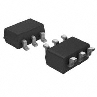
�1. Pin Configurations
Figure 1-1. Pinout of ATtiny4/5/9/10
SOT-23
(PCINT0/TPIDATA/OC0A/ADC0/AIN0) PB0 GND (PCINT1/TPICLK/CLKI/ICP0/OC0B/ADC1/AIN1) PB1 1 2 3 6 5 4 PB3 (RESET/PCINT3/ADC3) VCC PB2 (T0/CLKO/PCINT2/INT0/ADC2)
1.1
1.1.1
Pin Description
VCC Supply voltage.
1.1.2
GND Ground.
1.1.3
Port B (PB3..PB0) This is a 4-bit, bi-directional I/O port with internal pull-up resistors, individually selectable for each bit. The output buffers have symmetrical drive characteristics, with both high sink and source capability. As inputs, the port pins that are externally pulled low will source current if pullup resistors are activated. Port pins are tri-stated when a reset condition becomes active, even if the clock is not running. The port also serves the functions of various special features of the ATtiny4/5/9/10, as listed on page 36.
1.1.4
RESET Reset input. A low level on this pin for longer than the minimum pulse length will generate a reset, even if the clock is not running and provided the reset pin has not been disabled. The minimum pulse length is given in Table 16-4 on page 119. Shorter pulses are not guaranteed to generate a reset. The reset pin can also be used as a (weak) I/O pin.
2
ATtiny4/5/9/10
8127C–AVR–10/09
�ATtiny4/5/9/10
2. Overview
ATtiny4/5/9/10 are low-power CMOS 8-bit microcontrollers based on the compact AVR enhanced RISC architecture. By executing powerful instructions in a single clock cycle, the ATtiny4/5/9/10 achieve throughputs approaching 1 MIPS per MHz, allowing the system designer to optimize power consumption versus processing speed. Figure 2-1. Block Diagram
VCC RESET
PROGRAMMING LOGIC
PROGRAM COUNTER
INTERNAL OSCILLATOR
CALIBRATED OSCILLATOR
PROGRAM FLASH
STACK POINTER
WATCHDOG TIMER
TIMING AND CONTROL
INSTRUCTION REGISTER
SRAM
RESET FLAG REGISTER
INSTRUCTION DECODER
GENERAL PURPOSE REGISTERS
X Y Z
MCU STATUS REGISTER
CONTROL LINES
TIMER/ COUNTER0
INTERRUPT UNIT ALU
ISP INTERFACE
STATUS REGISTER 8-BIT DATA BUS
DATA REGISTER PORT B
DIRECTION REG. PORT B
ANALOG COMPARATOR
ADC
DRIVERS PORT B
PB3:0
GND
The AVR core combines a rich instruction set with 16 general purpose working registers and system registers. All registers are directly connected to the Arithmetic Logic Unit (ALU), allowing two independent registers to be accessed in one single instruction executed in one clock cycle. The resulting architecture is compact and code efficient while achieving throughputs up to ten times faster than conventional CISC microcontrollers.
3
8127C–AVR–10/09
�The ATtiny4/5/9/10 provide the following features: 512/1024 byte of In-System Programmable Flash, 32 bytes of SRAM, four general purpose I/O lines, 16 general purpose working registers, a 16-bit timer/counter with two PWM channels, internal and external interrupts, a programmable watchdog timer with internal oscillator, an internal calibrated oscillator, and four software selectable power saving modes. ATtiny5/10 are also equipped with a four-channel, 8-bit Analog to Digital Converter (ADC). Idle mode stops the CPU while allowing the SRAM, timer/counter, ADC (ATtiny5/10, only), analog comparator, and interrupt system to continue functioning. ADC Noise Reduction mode minimizes switching noise during ADC conversions by stopping the CPU and all I/O modules except the ADC. In Power-down mode registers keep their contents and all chip functions are disabled until the next interrupt or hardware reset. In Standby mode, the oscillator is running while the rest of the device is sleeping, allowing very fast start-up combined with low power consumption. The device is manufactured using Atmel’s high density non-volatile memory technology. The onchip, in-system programmable Flash allows program memory to be re-programmed in-system by a conventional, non-volatile memory programmer. The ATtiny4/5/9/10 AVR are supported by a suite of program and system development tools, including macro assemblers and evaluation kits.
2.1
Comparison of ATtiny4, ATtiny5, ATtiny9 and ATtiny10
A comparison of the devices is shown in Table 2-1. Table 2-1. Differences between ATtiny4, ATtiny5, ATtiny9 and ATtiny10
Flash 512 bytes 512 bytes 1024 bytes 1024 bytes ADC No Yes No Yes Signature 0x1E 0x8F 0x0A 0x1E 0x8F 0x09 0x1E 0x90 0x08 0x1E 0x90 0x03
Device ATtiny4 ATtiny5 ATtiny9 ATtiny10
4
ATtiny4/5/9/10
8127C–AVR–10/09
�ATtiny4/5/9/10
3. General Information
3.1 Resources
A comprehensive set of drivers, application notes, data sheets and descriptions on development tools are available for download at http://www.atmel.com/avr.
3.2
Code Examples
This documentation contains simple code examples that briefly show how to use various parts of the device. These code examples assume that the part specific header file is included before compilation. Be aware that not all C compiler vendors include bit definitions in the header files and interrupt handling in C is compiler dependent. Please confirm with the C compiler documentation for more details.
3.3
Data Retention
Reliability Qualification results show that the projected data retention failure rate is much less than 1 PPM over 20 years at 85°C or 100 years at 25°C.
3.4
Disclaimer
Typical values contained in this datasheet are based on simulations and characterization of other AVR microcontrollers manufactured on the same process technology. Min and Max values will be available after the device has been characterized.
5
8127C–AVR–10/09
�4. CPU Core
This section discusses the AVR core architecture in general. The main function of the CPU core is to ensure correct program execution. The CPU must therefore be able to access memories, perform calculations, control peripherals, and handle interrupts.
4.1
Architectural Overview
Figure 4-1. Block Diagram of the AVR Architecture
Data Bus 8-bit
Flash Program Memory
Program Counter
Status and Con trol
Instruction Reg ister
16 x 8 General Purpose Reg istrers
Interrupt Unit Watchdog Timer
Indirect Addressing
Instruction Decoder
Direct Addressing
ALU
Control Lines
Analog Comparator
ADC
Data SRA M
Timer/Counter 0
I/O Lines
In order to maximize performance and parallelism, the AVR uses a Harvard architecture – with separate memories and buses for program and data. Instructions in the program memory are executed with a single level pipelining. While one instruction is being executed, the next instruction is pre-fetched from the program memory. This concept enables instructions to be executed in every clock cycle. The program memory is In-System Reprogrammable Flash memory. The fast-access Register File contains 16 x 8-bit general purpose working registers with a single clock cycle access time. This allows single-cycle Arithmetic Logic Unit (ALU) operation. In a typical ALU operation, two operands are output from the Register File, the operation is executed, and the result is stored back in the Register File – in one clock cycle. 6
ATtiny4/5/9/10
8127C–AVR–10/09
�ATtiny4/5/9/10
Six of the 16 registers can be used as three 16-bit indirect address register pointers for data space addressing – enabling efficient address calculations. One of the these address pointers can also be used as an address pointer for look up tables in Flash program memory. These added function registers are the 16-bit X-, Y-, and Z-register, described later in this section. The ALU supports arithmetic and logic operations between registers or between a constant and a register. Single register operations can also be executed in the ALU. After an arithmetic operation, the Status Register is updated to reflect information about the result of the operation. Program flow is provided by conditional and unconditional jump and call instructions, capable of directly addressing the whole address space. Most AVR instructions have a single 16-bit word format but 32-bit wide instructions also exist. The actual instruction set varies, as some devices only implement a part of the instruction set. During interrupts and subroutine calls, the return address Program Counter (PC) is stored on the Stack. The Stack is effectively allocated in the general data SRAM, and consequently the Stack size is only limited by the SRAM size and the usage of the SRAM. All user programs must initialize the SP in the Reset routine (before subroutines or interrupts are executed). The Stack Pointer (SP) is read/write accessible in the I/O space. The data SRAM can easily be accessed through the four different addressing modes supported in the AVR architecture. The memory spaces in the AVR architecture are all linear and regular memory maps. A flexible interrupt module has its control registers in the I/O space with an additional Global Interrupt Enable bit in the Status Register. All interrupts have a separate Interrupt Vector in the Interrupt Vector table. The interrupts have priority in accordance with their Interrupt Vector position. The lower the Interrupt Vector address, the higher the priority. The I/O memory space contains 64 addresses for CPU peripheral functions as Control Registers, SPI, and other I/O functions. The I/O memory can be accessed as the data space locations, 0x0000 - 0x003F.
4.2
ALU – Arithmetic Logic Unit
The high-performance AVR ALU operates in direct connection with all the 16 general purpose working registers. Within a single clock cycle, arithmetic operations between general purpose registers or between a register and an immediate are executed. The ALU operations are divided into three main categories – arithmetic, logical, and bit-functions. Some implementations of the architecture also provide a powerful multiplier supporting both signed/unsigned multiplication and fractional format. See document “AVR Instruction Set” and section “Instruction Set Summary” on page 151 for a detailed description.
4.3
Status Register
The Status Register contains information about the result of the most recently executed arithmetic instruction. This information can be used for altering program flow in order to perform conditional operations. Note that the Status Register is updated after all ALU operations, as specified in document “AVR Instruction Set” and section “Instruction Set Summary” on page 151. This will in many cases remove the need for using the dedicated compare instructions, resulting in faster and more compact code. The Status Register is not automatically stored when entering an interrupt routine and restored when returning from an interrupt. This must be handled by software.
7
8127C–AVR–10/09
�4.4
General Purpose Register File
The Register File is optimized for the AVR Enhanced RISC instruction set. In order to achieve the required performance and flexibility, the following input/output schemes are supported by the Register File: • One 8-bit output operand and one 8-bit result input • Two 8-bit output operands and one 8-bit result input • One 16-bit output operand and one 16-bit result input Figure 4-2 below shows the structure of the 16 general purpose working registers in the CPU. Figure 4-2. AVR CPU General Purpose Working Registers
7 R16 R17 General Purpose Working Registers R18 … R26 R27 R28 R29 R30 R31 X-register Low Byte X-register High Byte Y-register Low Byte Y-register High Byte Z-register Low Byte Z-register High Byte 0
Note:
A typical implementation of the AVR register file includes 32 general prupose registers but ATtiny4/5/9/10 implement only 16 registers. For reasons of compatibility the registers are numbered R16...R31, not R0...R15.
Most of the instructions operating on the Register File have direct access to all registers, and most of them are single cycle instructions. 4.4.1 The X-register, Y-register, and Z-register Registers R26..R31 have some added functions to their general purpose usage. These registers are 16-bit address pointers for indirect addressing of the data space. The three indirect address registers X, Y, and Z are defined as described in Figure 4-3.
8
ATtiny4/5/9/10
8127C–AVR–10/09
�ATtiny4/5/9/10
Figure 4-3. The X-, Y-, and Z-registers
15 X-register 7 R27 XH 0 7 R26 XL 0 0
15 Y-register 7
YH 0 R29 7
YL
0 0
R28
15 Z-register 7
ZH 0 R31 7
ZL
0 0
R30
In different addressing modes these address registers function as automatic increment and automatic decrement (see document “AVR Instruction Set” and section “Instruction Set Summary” on page 151 for details).
4.5
Stack Pointer
The Stack is mainly used for storing temporary data, for storing local variables and for storing return addresses after interrupts and subroutine calls. The Stack Pointer Register always points to the top of the Stack. Note that the Stack is implemented as growing from higher memory locations to lower memory locations. This implies that a Stack PUSH command decreases the Stack Pointer. The Stack Pointer points to the data SRAM Stack area where the Subroutine and Interrupt Stacks are located. This Stack space in the data SRAM must be defined by the program before any subroutine calls are executed or interrupts are enabled. The Stack Pointer must be set to point above 0x40. The Stack Pointer is decremented by one when data is pushed onto the Stack with the PUSH instruction, and it is decremented by two when the return address is pushed onto the Stack with subroutine call or interrupt. The Stack Pointer is incremented by one when data is popped from the Stack with the POP instruction, and it is incremented by two when data is popped from the Stack with return from subroutine RET or return from interrupt RETI. The AVR Stack Pointer is implemented as two 8-bit registers in the I/O space. The number of bits actually used is implementation dependent. Note that the data space in some implementations of the AVR architecture is so small that only SPL is needed. In this case, the SPH Register will not be present.
4.6
Instruction Execution Timing
This section describes the general access timing concepts for instruction execution. The AVR CPU is driven by the CPU clock clkCPU, directly generated from the selected clock source for the chip. No internal clock division is used.
9
8127C–AVR–10/09
�Figure 4-4.
The Parallel Instruction Fetches and Instruction Executions
T1 T2 T3 T4
clkCPU 1st Instruction Fetch 1st Instruction Execute 2nd Instruction Fetch 2nd Instruction Execute 3rd Instruction Fetch 3rd Instruction Execute 4th Instruction Fetch
Figure 4-4 shows the parallel instruction fetches and instruction executions enabled by the Harvard architecture and the fast access Register File concept. This is the basic pipelining concept to obtain up to 1 MIPS per MHz with the corresponding unique results for functions per cost, functions per clocks, and functions per power-unit. Figure 4-5 shows the internal timing concept for the Register File. In a single clock cycle an ALU operation using two register operands is executed, and the result is stored back to the destination register. Figure 4-5. Single Cycle ALU Operation
T1 T2 T3 T4
clkCPU Total Execution Time Register Operands Fetch ALU Operation Execute Result Write Back
4.7
Reset and Interrupt Handling
The AVR provides several different interrupt sources. These interrupts and the separate Reset Vector each have a separate Program Vector in the program memory space. All interrupts are assigned individual enable bits which must be written logic one together with the Global Interrupt Enable bit in the Status Register in order to enable the interrupt. The lowest addresses in the program memory space are by default defined as the Reset and Interrupt Vectors. The complete list of vectors is shown in “Interrupts” on page 35. The list also determines the priority levels of the different interrupts. The lower the address the higher is the priority level. RESET has the highest priority, and next is INT0 – the External Interrupt Request 0. When an interrupt occurs, the Global Interrupt Enable I-bit is cleared and all interrupts are disabled. The user software can write logic one to the I-bit to enable nested interrupts. All enabled
10
ATtiny4/5/9/10
8127C–AVR–10/09
�ATtiny4/5/9/10
interrupts can then interrupt the current interrupt routine. The I-bit is automatically set when a Return from Interrupt instruction – RETI – is executed. There are basically two types of interrupts. The first type is triggered by an event that sets the Interrupt Flag. For these interrupts, the Program Counter is vectored to the actual Interrupt Vector in order to execute the interrupt handling routine, and hardware clears the corresponding Interrupt Flag. Interrupt Flags can also be cleared by writing a logic one to the flag bit position(s) to be cleared. If an interrupt condition occurs while the corresponding interrupt enable bit is cleared, the Interrupt Flag will be set and remembered until the interrupt is enabled, or the flag is cleared by software. Similarly, if one or more interrupt conditions occur while the Global Interrupt Enable bit is cleared, the corresponding Interrupt Flag(s) will be set and remembered until the Global Interrupt Enable bit is set, and will then be executed by order of priority. The second type of interrupts will trigger as long as the interrupt condition is present. These interrupts do not necessarily have Interrupt Flags. If the interrupt condition disappears before the interrupt is enabled, the interrupt will not be triggered. When the AVR exits from an interrupt, it will always return to the main program and execute one more instruction before any pending interrupt is served. Note that the Status Register is not automatically stored when entering an interrupt routine, nor restored when returning from an interrupt routine. This must be handled by software. When using the CLI instruction to disable interrupts, the interrupts will be immediately disabled. No interrupt will be executed after the CLI instruction, even if it occurs simultaneously with the CLI instruction. When using the SEI instruction to enable interrupts, the instruction following SEI will be executed before any pending interrupts, as shown in the following example. Assembly Code Example
sei sleep ; set Global Interrupt Enable ; enter sleep, waiting for interrupt ; note: will enter sleep before any pending interrupt(s) Note: See “Code Examples” on page 5.
4.7.1
Interrupt Response Time The interrupt execution response for all the enabled AVR interrupts is four clock cycles minimum. After four clock cycles the Program Vector address for the actual interrupt handling routine is executed. During this four clock cycle period, the Program Counter is pushed onto the Stack. The vector is normally a jump to the interrupt routine, and this jump takes three clock cycles. If an interrupt occurs during execution of a multi-cycle instruction, this instruction is completed before the interrupt is served. If an interrupt occurs when the MCU is in sleep mode, the interrupt execution response time is increased by four clock cycles. This increase comes in addition to the start-up time from the selected sleep mode. A return from an interrupt handling routine takes four clock cycles. During these four clock cycles, the Program Counter (two bytes) is popped back from the Stack, the Stack Pointer is incremented by two, and the I-bit in SREG is set.
11
8127C–AVR–10/09
�4.8
4.8.1
Register Description
CCP – Configuration Change Protection Register
Bit 0x3C Read/Write Initial Value W 0 W 0 W 0 W 0 7 6 5 4 CCP[7:0] W 0 W 0 W 0 W 0 3 2 1 0 CCP
• Bits 7:0 – CCP[7:0] – Configuration Change Protection In order to change the contents of a protected I/O register the CCP register must first be written with the correct signature. After CCP is written the protected I/O registers may be written to during the next four CPU instruction cycles. All interrupts are ignored during these cycles. After these cycles interrupts are automatically handled again by the CPU, and any pending interrupts will be executed according to their priority. When the protected I/O register signature is written, CCP[0] will read as one as long as the protected feature is enabled, while CCP[7:1] will always read as zero. Table 4-1 shows the signatures that are in recognised. Table 4-1.
Signature 0xD8
Signatures Recognised by the Configuration Change Protection Register
Group IOREG: CLKMSR, CLKPSR, WDTCSR Description Protected I/O register
4.8.2
SPH and SPL — Stack Pointer Register
Bit 0x3E 0x3D Read/Write Read/Write Initial Value Initial Value 15 SP15 SP7 7 R/W R/W
RAMEND RAMEND
14 SP14 SP6 6 R/W R/W
RAMEND RAMEND
13 SP13 SP5 5 R/W R/W
RAMEND RAMEND
12 SP12 SP4 4 R/W R/W
RAMEND RAMEND
11 SP11 SP3 3 R/W R/W
RAMEND RAMEND
10 SP10 SP2 2 R/W R/W
RAMEND RAMEND
9 SP9 SP1 1 R/W R/W
RAMEND RAMEND
8 SP8 SP0 0 R/W R/W
RAMEND RAMEND
SPH SPL
4.8.3
SREG – Status Register
Bit 0x3F Read/Write Initial Value 7 I R/W 0 6 T R/W 0 5 H R/W 0 4 S R/W 0 3 V R/W 0 2 N R/W 0 1 Z R/W 0 0 C R/W 0 SREG
• Bit 7 – I: Global Interrupt Enable The Global Interrupt Enable bit must be set for the interrupts to be enabled. The individual interrupt enable control is then performed in separate control registers. If the Global Interrupt Enable Register is cleared, none of the interrupts are enabled independent of the individual interrupt enable settings. The I-bit is cleared by hardware after an interrupt has occurred, and is set by the RETI instruction to enable subsequent interrupts. The I-bit can also be set and cleared by the application with the SEI and CLI instructions, as described in the document “AVR Instruction Set” and “Instruction Set Summary” on page 151.
12
ATtiny4/5/9/10
8127C–AVR–10/09
�ATtiny4/5/9/10
• Bit 6 – T: Bit Copy Storage The Bit Copy instructions BLD (Bit LoaD) and BST (Bit STore) use the T-bit as source or destination for the operated bit. A bit from a register in the Register File can be copied into T by the BST instruction, and a bit in T can be copied into a bit in a register in the Register File by the BLD instruction. • Bit 5 – H: Half Carry Flag The Half Carry Flag H indicates a Half Carry in some arithmetic operations. Half Carry is useful in BCD arithmetic. See document “AVR Instruction Set” and section “Instruction Set Summary” on page 151 for detailed information. • Bit 4 – S: Sign Bit, S = N ⊕ V The S-bit is always an exclusive or between the Negative Flag N and the Two’s Complement Overflow Flag V. See document “AVR Instruction Set” and section “Instruction Set Summary” on page 151 for detailed information. • Bit 3 – V: Two’s Complement Overflow Flag The Two’s Complement Overflow Flag V supports two’s complement arithmetics. See document “AVR Instruction Set” and section “Instruction Set Summary” on page 151 for detailed information. • Bit 2 – N: Negative Flag The Negative Flag N indicates a negative result in an arithmetic or logic operation. See document “AVR Instruction Set” and section “Instruction Set Summary” on page 151 for detailed information. • Bit 1 – Z: Zero Flag The Zero Flag Z indicates a zero result in an arithmetic or logic operation. See document “AVR Instruction Set” and section “Instruction Set Summary” on page 151 for detailed information. • Bit 0 – C: Carry Flag The Carry Flag C indicates a carry in an arithmetic or logic operation. See document “AVR Instruction Set” and section “Instruction Set Summary” on page 151 for detailed information.
13
8127C–AVR–10/09
�5. Memories
This section describes the different memories in the ATtiny4/5/9/10. Devices have two main memory areas, the program memory space and the data memory space.
5.1
In-System Re-programmable Flash Program Memory
The ATtiny4/5/9/10 contain 512/1024 bytes of on-chip, in-system reprogrammable Flash memory for program storage. Since all AVR instructions are 16 or 32 bits wide, the Flash is organized as 256/512 x 16. The Flash memory has an endurance of at least 10,000 write/erase cycles. The ATtiny4/5/9/10 Program Counter (PC) is 9 bits wide, thus capable of addressing the 256/512 program memory locations, starting at 0x000. “Memory Programming” on page 107 contains a detailed description on Flash data serial downloading. Constant tables can be allocated within the entire address space of program memory. Since program memory can not be accessed directly, it has been mapped to the data memory. The mapped program memory begins at byte address 0x4000 in data memory (see Figure 5-1 on page 15). Although programs are executed starting from address 0x000 in program memory it must be addressed starting from 0x4000 when accessed via the data memory. Internal write operations to Flash program memory have been disabled and program memory therefore appears to firmware as read-only. Flash memory can still be written to externally but internal write operations to the program memory area will not be succesful. Timing diagrams of instruction fetch and execution are presented in “Instruction Execution Timing” on page 9.
5.2
Data Memory
Data memory locations include the I/O memory, the internal SRAM memory, the non-volatile memory lock bits, and the Flash memory. See Figure 5-1 on page 15 for an illustration on how the ATtiny4/5/9/10 memory space is organized. The first 64 locations are reserved for I/O memory, while the following 32 data memory locations address the internal data SRAM. The non-volatile memory lock bits and all the Flash memory sections are mapped to the data memory space. These locations appear as read-only for device firmware. The four different addressing modes for data memory are direct, indirect, indirect with pre-decrement, and indirect with post-increment. In the register file, registers R26 to R31 function as pointer registers for indirect addressing. The IN and OUT instructions can access all 64 locations of I/O memory. Direct addressing using the LDS and STS instructions reaches the 128 locations between 0x0040 and 0x00BF. The indirect addressing reaches the entire data memory space. When using indirect addressing modes with automatic pre-decrement and post-increment, the address registers X, Y, and Z are decremented or incremented.
14
ATtiny4/5/9/10
8127C–AVR–10/09
�ATtiny4/5/9/10
Figure 5-1. Data Memory Map (Byte Addressing)
I/O SPACE SRAM DATA MEMORY (reserved) NVM LOCK BITS (reserved) CONFIGURATION BITS (reserved) CALIBRATION BITS (reserved) DEVICE ID BITS (reserved) FLASH PROGRAM MEMORY (reserved)
0x0000 ... 0x003F 0x0040 ... 0x005F 0x0060 ... 0x3EFF 0x3F00 ... 0x3F01 0x3F02 ... 0x3F3F 0x3F40 ... 0x3F41 0x3F42 ... 0x3F7F 0x3F80 ... 0x3F81 0x3F82 ... 0x3FBF 0x3FC0 ... 0x3FC3 0x3FC4 ... 0x3FFF 0x4000 ... 0x41FF/0x43FF 0x4400 ... 0xFFFF
5.2.1
Data Memory Access Times This section describes the general access timing concepts for internal memory access. The internal data SRAM access is performed in two clkCPU cycles as described in Figure 5-2. Figure 5-2. On-chip Data SRAM Access Cycles
T1 T2 T3
clkCPU Address Data WR Data RD
Compute Address Address valid
Memory Access Instruction
Next Instruction
Read
Write
15
8127C–AVR–10/09
�5.3
I/O Memory
The I/O space definition of the ATtiny4/5/9/10 is shown in “Register Summary” on page 149. All ATtiny4/5/9/10 I/Os and peripherals are placed in the I/O space. All I/O locations may be accessed using the LD and ST instructions, enabling data transfer between the 16 general purpose working registers and the I/O space. I/O Registers within the address range 0x00 - 0x1F are directly bit-accessible using the SBI and CBI instructions. In these registers, the value of single bits can be checked by using the SBIS and SBIC instructions. See document “AVR Instruction Set” and section “Instruction Set Summary” on page 151 for more details. When using the I/O specific commands IN and OUT, the I/O addresses 0x00 - 0x3F must be used. For compatibility with future devices, reserved bits should be written to zero if accessed. Reserved I/O memory addresses should never be written. Some of the status flags are cleared by writing a logical one to them. Note that CBI and SBI instructions will only operate on the specified bit, and can therefore be used on registers containing such status flags. The CBI and SBI instructions work on registers in the address range 0x00 to 0x1F, only. The I/O and Peripherals Control Registers are explained in later sections.
16
ATtiny4/5/9/10
8127C–AVR–10/09
�ATtiny4/5/9/10
6. Clock System
Figure 6-1 presents the principal clock systems and their distribution in ATtiny4/5/9/10. All of the clocks need not be active at a given time. In order to reduce power consumption, the clocks to modules not being used can be halted by using different sleep modes and power reduction register bits, as described in “Power Management and Sleep Modes” on page 23. The clock systems is detailed below. Figure 6-1. Clock Distribution
ANALOG-TO-DIGITAL CONVERTER clk ADC GENERAL I/O MODULES clk I/O CPU CORE RAM NVM
clk CPU
clk NVM
CLOCK CONTROL UNIT
SOURCE CLOCK
RESET LOGIC
WATCHDOG CLOCK
CLOCK PRESCALER
WATCHDOG TIMER
CLOCK SWITCH
EXTERNAL CLOCK
WATCHDOG OSCILLATOR
CALIBRATED OSCILLATOR
6.1
6.1.1
Clock Subsystems
The clock subsystems are detailed in the sections below. CPU Clock – clkCPU The CPU clock is routed to parts of the system concerned with operation of the AVR Core. Examples of such modules are the General Purpose Register File, the System Registers and the SRAM data memory. Halting the CPU clock inhibits the core from performing general operations and calculations. I/O Clock – clkI/O The I/O clock is used by the majority of the I/O modules, like Timer/Counter. The I/O clock is also used by the External Interrupt module, but note that some external interrupts are detected by asynchronous logic, allowing such interrupts to be detected even if the I/O clock is halted. NVM clock - clkNVM The NVM clock controls operation of the Non-Volatile Memory Controller. The NVM clock is usually active simultaneously with the CPU clock. 17
6.1.2
6.1.3
8127C–AVR–10/09
�6.1.4
ADC Clock – clkADC The ADC is provided with a dedicated clock domain. This allows halting the CPU and I/O clocks in order to reduce noise generated by digital circuitry. This gives more accurate ADC conversion results. The ADC is available in ATtiny5/10, only.
6.2
Clock Sources
All synchronous clock signals are derived from the main clock. The device has three alternative sources for the main clock, as follows: • Calibrated Internal 8 MHz Oscillator (see page 18) • External Clock (see page 18) • Internal 128 kHz Oscillator (see page 19) See Table 6-3 on page 21 on how to select and change the active clock source.
6.2.1
Calibrated Internal 8 MHz Oscillator The calibrated internal oscillator provides an approximately 8 MHz clock signal. Though voltage and temperature dependent, this clock can be very accurately calibrated by the user. See Table 16-2 on page 118, Figure 17-39 on page 142 and Figure 17-40 on page 142 for more details. This clock may be selected as the main clock by setting the Clock Main Select bits CLKMS[1:0] in CLKMSR to 0b00. Once enabled, the oscillator will operate with no external components. During reset, hardware loads the calibration byte into the OSCCAL register and thereby automatically calibrates the oscillator. The accuracy of this calibration is shown as Factory calibration in Table 16-2 on page 118. When this oscillator is used as the main clock, the watchdog oscillator will still be used for the watchdog timer and reset time-out. For more information on the pre-programmed calibration value, see section “Calibration Section” on page 110.
6.2.2
External Clock To use the device with an external clock source, CLKI should be driven as shown in Figure 6-2. The external clock is selected as the main clock by setting CLKMS[1:0] bits in CLKMSR to 0b10. Figure 6-2. External Clock Drive Configuration
EXTERNAL CLOCK SIGNAL
CLKI
GND
When applying an external clock, it is required to avoid sudden changes in the applied clock frequency to ensure stable operation of the MCU. A variation in frequency of more than 2% from one clock cycle to the next can lead to unpredictable behavior. It is required to ensure that the MCU is kept in reset during such changes in the clock frequency.
18
ATtiny4/5/9/10
8127C–AVR–10/09
�ATtiny4/5/9/10
6.2.3 Internal 128 kHz Oscillator The internal 128 kHz oscillator is a low power oscillator providing a clock of 128 kHz. The frequency depends on supply voltage, temperature and batch variations. This clock may be select as the main clock by setting the CLKMS[1:0] bits in CLKMSR to 0b01. Switching Clock Source The main clock source can be switched at run-time using the “CLKMSR – Clock Main Settings Register” on page 21. When switching between any clock sources, the clock system ensures that no glitch occurs in the main clock. Default Clock Source The calibrated internal 8 MHz oscillator is always selected as main clock when the device is powered up or has been reset. The synchronous system clock is the main clock divided by 8, controlled by the System Clock Prescaler. The Clock Prescaler Select Bits can be written later to change the system clock frequency. See “System Clock Prescaler”.
6.2.4
6.2.5
6.3
System Clock Prescaler
The system clock is derived from the main clock via the System Clock Prescaler. The system clock can be divided by setting the “CLKPSR – Clock Prescale Register” on page 22. The system clock prescaler can be used to decrease power consumption at times when requirements for processing power is low or to bring the system clock within limits of maximum frequency. The prescaler can be used with all main clock source options, and it will affect the clock frequency of the CPU and all synchronous peripherals. The System Clock Prescaler can be used to implement run-time changes of the internal clock frequency while still ensuring stable operation.
6.3.1
Switching Prescaler Setting When switching between prescaler settings, the system clock prescaler ensures that no glitch occurs in the system clock and that no intermediate frequency is higher than neither the clock frequency corresponding the previous setting, nor the clock frequency corresponding to the new setting. The ripple counter that implements the prescaler runs at the frequency of the main clock, which may be faster than the CPU's clock frequency. Hence, it is not possible to determine the state of the prescaler - even if it were readable, and the exact time it takes to switch from one clock division to another cannot be exactly predicted. From the time the CLKPS values are written, it takes between T1 + T2 and T1 + 2*T2 before the new clock frequency is active. In this interval, two active clock edges are produced. Here, T1 is the previous clock period, and T2 is the period corresponding to the new prescaler setting.
19
8127C–AVR–10/09
�6.4
6.4.1
Starting
Starting from Reset The internal reset is immediately asserted when a reset source goes active. The internal reset is kept asserted until the reset source is released and the start-up sequence is completed. The start-up sequence includes three steps, as follows. 1. The first step after the reset source has been released consists of the device counting the reset start-up time. The purpose of this reset start-up time is to ensure that supply voltage has reached sufficient levels. The reset start-up time is counted using the internal 128 kHz oscillator. See Table 6-1 for details of reset start-up time. Note that the actual supply voltage is not monitored by the start-up logic. The device will count until the reset start-up time has elapsed even if the device has reached sufficient supply voltage levels earlier. 2. The second step is to count the oscillator start-up time, which ensures that the calibrated internal oscillator has reached a stable state before it is used by the other parts of the system. The calibrated internal oscillator needs to oscillate for a minimum number of cycles before it can be considered stable. See Table 6-1 for details of the oscillator start-up time. 3. The last step before releasing the internal reset is to load the calibration and the configuration values from the Non-Volatile Memory to configure the device properly. The configuration time is listed in Table 6-1. Table 6-1.
Reset 64 ms Notes:
Start-up Times when Using the Internal Calibrated Oscillator
Oscillator 6 cycles Configuration 21 cycles Total start-up time 64 ms + 6 oscillator cycles + 21 system clock cycles (1)
1. After powering up the device or after a reset the system clock is automatically set to calibrated internal 8 MHz oscillator, divided by 8
6.4.2
Starting from Power-Down Mode When waking up from Power-Down sleep mode, the supply voltage is assumed to be at a sufficient level and only the oscillator start-up time is counted to ensure the stable operation of the oscillator. The oscillator start-up time is counted on the selected main clock, and the start-up time depends on the clock selected. See Table 6-2 for details. Table 6-2. Start-up Time from Power-Down Sleep Mode.
Oscillator start-up time 6 cycles Notes: Total start-up time 6 oscillator cycles (1)
1. The start-up time is measured in main clock oscillator cycles.
6.4.3
Starting from Idle / ADC Noise Reduction / Standby Mode When waking up from Idle, ADC Noise Reduction or Standby Mode, the oscillator is already running and no oscillator start-up time is introduced. The ADC is available in ATtiny5/10, only.
20
ATtiny4/5/9/10
8127C–AVR–10/09
�ATtiny4/5/9/10
6.5
6.5.1
Register Description
CLKMSR – Clock Main Settings Register
Bit 0x37 Read/Write Initial Value 7 – R 0 6 – R 0 5 – R 0 4 – R 0 3 – R 0 2 – R 0 1 CLKMS1 R/W 0 0 CLKMS0 R/W 0 CLKMSR
• Bit 7:2 – Res: Reserved Bits These bits are reserved and always read zero. • Bit 1:0 – CLKMS[1:0]: Clock Main Select Bits These bits select the main clock source of the system. The bits can be written at run-time to switch the source of the main clock. The clock system ensures glitch free switching of the main clock source. The main clock alternatives are shown in Table 6-3. Table 6-3.
CLKM1 0 0 1 1
Selection of Main Clock
CLKM0 0 1 0 1 Main Clock Source Calibrated Internal 8 MHzOscillator Internal 128 kHz Oscillator (WDT Oscillator) External clock Reserved
To avoid unintentional switching of main clock source, a protected change sequence must be followed to change the CLKMS bits, as follows: 1. Write the signature for change enable of protected I/O register to register CCP 2. Within four instruction cycles, write the CLKMS bits with the desired value 6.5.2 OSCCAL – Oscillator Calibration Register
.
Bit 0x39 Read/Write Initial Value
7 CAL7 R/W 0
6 CAL6 R/W 0
5 CAL5 R/W 0
4 CAL4 R/W 0
3 CAL3 R/W 0
2 CAL2 R/W 0
1 CAL1 R/W 0
0 CAL0 R/W 0 OSCCAL
• Bits 7:0 – CAL[7:0]: Oscillator Calibration Value The oscillator calibration register is used to trim the calibrated internal oscillator and remove process variations from the oscillator frequency. A pre-programmed calibration value is automatically written to this register during chip reset, giving the factory calibrated frequency as specified in Table 16-2, “Calibration Accuracy of Internal RC Oscillator,” on page 118. The application software can write this register to change the oscillator frequency. The oscillator can be calibrated to frequencies as specified in Table 16-2, “Calibration Accuracy of Internal RC Oscillator,” on page 118. Calibration outside the range given is not guaranteed. The CAL[7:0] bits are used to tune the frequency of the oscillator. A setting of 0x00 gives the lowest frequency, and a setting of 0xFF gives the highest frequency.
21
8127C–AVR–10/09
�6.5.3
CLKPSR – Clock Prescale Register
Bit 0x36 Read/Write Initial Value 7 – R 0 6 – R 0 5 – R 0 4 – R 0 3 CLKPS3 R/W 0 2 CLKPS2 R/W 0 1 CLKPS1 R/W 1 0 CLKPS0 R/W 1 CLKPSR
• Bits 7:4 – Res: Reserved Bits These bits are reserved and will always read as zero. • Bits 3:0 – CLKPS[3:0]: Clock Prescaler Select Bits 3 - 0 These bits define the division factor between the selected clock source and the internal system clock. These bits can be written at run-time to vary the clock frequency and suit the application requirements. As the prescaler divides the master clock input to the MCU, the speed of all synchronous peripherals is reduced accordingly. The division factors are given in Table 6-4. Table 6-4.
CLKPS3 0 0 0 0 0 0 0 0 1 1 1 1 1 1 1 1
Clock Prescaler Select
CLKPS2 0 0 0 0 1 1 1 1 0 0 0 0 1 1 1 1 CLKPS1 0 0 1 1 0 0 1 1 0 0 1 1 0 0 1 1 CLKPS0 0 1 0 1 0 1 0 1 0 1 0 1 0 1 0 1 Clock Division Factor 1 2 4 8 (default) 16 32 64 128 256 Reserved Reserved Reserved Reserved Reserved Reserved Reserved
To avoid unintentional changes of clock frequency, a protected change sequence must be followed to change the CLKPS bits: 1. Write the signature for change enable of protected I/O register to register CCP 2. Within four instruction cycles, write the desired value to CLKPS bits At start-up, CLKPS bits are reset to 0b0011 to select the clock division factor of 8. If the selected clock source has a frequency higher than the maximum allowed the application software must make sure a sufficient division factor is used. To make sure the write procedure is not interrupted, interrupts must be disabled when changing prescaler settings.
22
ATtiny4/5/9/10
8127C–AVR–10/09
�ATtiny4/5/9/10
7. Power Management and Sleep Modes
The high performance and industry leading code efficiency makes the AVR microcontrollers an ideal choise for low power applications. In addition, sleep modes enable the application to shut down unused modules in the MCU, thereby saving power. The AVR provides various sleep modes allowing the user to tailor the power consumption to the application’s requirements.
7.1
Sleep Modes
Figure 6-1 on page 17 presents the different clock systems and their distribution in ATtiny4/5/9/10. The figure is helpful in selecting an appropriate sleep mode. Table 7-1 shows the different sleep modes and their wake up sources. Table 7-1. Active Clock Domains and Wake-up Sources in Different Sleep Modes
Active Clock Domains Oscillators Main Clock Source Enabled INT0 and Pin Change Wake-up Sources VLM Interrupt X X
Sleep Mode Idle ADC Noise Reduction Standby Power-down Note:
X
X X
X X X
X X (2) X X
(2) (2)
X X
X
1. The ADC is available in ATtiny5/10, only 2. For INT0, only level interrupt.
To enter any of the four sleep modes, the SE bits in SMCR must be written to logic one and a SLEEP instruction must be executed. The SM2:0 bits in the SMCR register select which sleep mode (Idle, ADC Noise Reduction, Standby or Power-down) will be activated by the SLEEP instruction. See Table 7-2 for a summary. If an enabled interrupt occurs while the MCU is in a sleep mode, the MCU wakes up. The MCU is then halted for four cycles in addition to the start-up time, executes the interrupt routine, and resumes execution from the instruction following SLEEP. The contents of the Register File and SRAM are unaltered when the device wakes up from sleep. If a reset occurs during sleep mode, the MCU wakes up and executes from the Reset Vector. Note that if a level triggered interrupt is used for wake-up the changed level must be held for some time to wake up the MCU (and for the MCU to enter the interrupt service routine). See “External Interrupts” on page 36 for details. 7.1.1 Idle Mode When bits SM2:0 are written to 000, the SLEEP instruction makes the MCU enter Idle mode, stopping the CPU but allowing the analog comparator, timer/counter, watchdog, and the interrupt system to continue operating. This sleep mode basically halts clk CPU and clkNVM, while allowing the other clocks to run. Idle mode enables the MCU to wake up from external triggered interrupts as well as internal ones like the timer overflow. If wake-up from the analog comparator interrupt is not required, the 23
8127C–AVR–10/09
Watchdog Interrupt X X X X
Other I/O
clkADC (1)
ADC (1)
clkNVM
clkCPU
clkIO
�analog comparator can be powered down by setting the ACD bit in “ACSR – Analog Comparator Control and Status Register” on page 81. This will reduce power consumption in idle mode. If the ADC is enabled (ATtiny5/10, only), a conversion starts automatically when this mode is entered. 7.1.2 ADC Noise Reduction Mode When bits SM2:0 are written to 001, the SLEEP instruction makes the MCU enter ADC Noise Reduction mode, stopping the CPU but allowing the ADC, the external interrupts, and the watchdog to continue operating (if enabled). This sleep mode halts clkI/O, clkCPU, and clkNVM, while allowing the other clocks to run. This mode improves the noise environment for the ADC, enabling higher resolution measurements. If the ADC is enabled, a conversion starts automatically when this mode is entered. This mode is available in all devices, although only ATtiny5/10 are equipped with an ADC. 7.1.3 Power-down Mode When bits SM2:0 are written to 010, the SLEEP instruction makes the MCU enter Power-down mode. In this mode, the oscillator is stopped, while the external interrupts, and the watchdog continue operating (if enabled). Only a watchdog reset, an external level interrupt on INT0, or a pin change interrupt can wake up the MCU. This sleep mode halts all generated clocks, allowing operation of asynchronous modules only. Standby Mode When bits SM2:0 are written to 100, the SLEEP instruction makes the MCU enter Standby mode. This mode is identical to Power-down with the exception that the oscillator is kept running. This reduces wake-up time, because the oscillator is already running and doesn't need to be started up.
7.1.4
7.2
Power Reduction Register
The Power Reduction Register (PRR), see “PRR – Power Reduction Register” on page 26, provides a method to reduce power consumption by stopping the clock to individual peripherals. When the clock for a peripheral is stopped then: • The current state of the peripheral is frozen. • The associated registers can not be read or written. • Resources used by the peripheral will remain occupied. The peripheral should in most cases be disabled before stopping the clock. Clearing the PRR bit wakes up the peripheral and puts it in the same state as before shutdown. Peripheral shutdown can be used in Idle mode and Active mode to significantly reduce the overall power consumption. See “Supply Current of I/O Modules” on page 122 for examples. In all other sleep modes, the clock is already stopped.
7.3
Minimizing Power Consumption
There are several issues to consider when trying to minimize the power consumption in an AVR Core controlled system. In general, sleep modes should be used as much as possible, and the sleep mode should be selected so that as few as possible of the device’s functions are operating. All functions not needed should be disabled. In particular, the following modules may need special consideration when trying to achieve the lowest possible power consumption.
24
ATtiny4/5/9/10
8127C–AVR–10/09
�ATtiny4/5/9/10
7.3.1 Analog Comparator When entering Idle mode, the analog comparator should be disabled if not used. In the powerdown mode, the analog comparator is automatically disabled. See “Analog Comparator” on page 81 for further details. Analog to Digital Converter If enabled, the ADC will be enabled in all sleep modes. To save power, the ADC should be disabled before entering any sleep mode. When the ADC is turned off and on again, the next conversion will be an extended conversion. See “Analog to Digital Converter” on page 83 for details on ADC operation. The ADC is available in ATtiny5/10, only. 7.3.3 Watchdog Timer If the Watchdog Timer is not needed in the application, this module should be turned off. If the Watchdog Timer is enabled, it will be enabled in all sleep modes, and hence, always consume power. In the deeper sleep modes, this will contribute significantly to the total current consumption. Refer to “Watchdog Timer” on page 30 for details on how to configure the Watchdog Timer. Port Pins When entering a sleep mode, all port pins should be configured to use minimum power. The most important thing is then to ensure that no pins drive resistive loads. In sleep modes where the I/O clock (clkI/O) is stopped, the input buffers of the device will be disabled. This ensures that no power is consumed by the input logic when not needed. In some cases, the input logic is needed for detecting wake-up conditions, and it will then be enabled. Refer to the section “Digital Input Enable and Sleep Modes” on page 44 for details on which pins are enabled. If the input buffer is enabled and the input signal is left floating or has an analog signal level close to VCC/2, the input buffer will use excessive power. For analog input pins, the digital input buffer should be disabled at all times. An analog signal level close to VCC/2 on an input pin can cause significant current even in active mode. Digital input buffers can be disabled by writing to the Digital Input Disable Register (DIDR0). Refer to “DIDR0 – Digital Input Disable Register 0” on page 82 for details.
7.3.2
7.3.4
7.4
7.4.1
Register Description
SMCR – Sleep Mode Control Register The SMCR Control Register contains control bits for power management.
Bit 0x3A Read/Write Initial Value 7 – R 0 6 – R 0 5 – R 0 4 – R 0 3 SM2 R/W 0 2 SM1 R/W 0 1 SM0 R/W 0 0 SE R/W 0 SMCR
• Bits 7:4 – Res: Reserved Bits These bits are reserved and will always read zero.
25
8127C–AVR–10/09
�• Bits 3:1 – SM2..SM0: Sleep Mode Select Bits 2..0 These bits select between available sleep modes, as shown in Table 7-2. Table 7-2.
SM2 0 0 0 0 1 1 1 1 Note:
Sleep Mode Select
SM1 0 0 1 1 0 0 1 1 SM0 0 1 0 1 0 1 0 1 Sleep Mode Idle ADC noise reduction (1) Power-down Reserved Standby Reserved Reserved Reserved
1. This mode is available in all devices, although only ATtiny5/10 are equipped with an ADC
• Bit 0 – SE: Sleep Enable The SE bit must be written to logic one to make the MCU enter the sleep mode when the SLEEP instruction is executed. To avoid the MCU entering the sleep mode unless it is the programmer’s purpose, it is recommended to write the Sleep Enable (SE) bit to one just before the execution of the SLEEP instruction and to clear it immediately after waking up. 7.4.2 PRR – Power Reduction Register
Bit 0x35 Read/Write Initial Value 7 – R 0 6 – R 0 5 – R 0 4 – R 0 3 – R 0 2 – R 0 1 PRADC R/W 0 0 PRTIM0 R/W 0 PRR
• Bits 7:2 – Res: Reserved Bits These bits are reserved and will always read zero. • Bit 1 – PRADC: Power Reduction ADC Writing a logic one to this bit shuts down the ADC. The ADC must be disabled before shut down. The analog comparator cannot use the ADC input MUX when the ADC is shut down. The ADC is available in ATtiny5/10, only. • Bit 0 – PRTIM0: Power Reduction Timer/Counter0 Writing a logic one to this bit shuts down the Timer/Counter0 module. When the Timer/Counter0 is enabled, operation will continue like before the shutdown.
26
ATtiny4/5/9/10
8127C–AVR–10/09
�ATtiny4/5/9/10
8. System Control and Reset
8.1 Resetting the AVR
During reset, all I/O registers are set to their initial values, and the program starts execution from the Reset Vector. The instruction placed at the Reset Vector must be a RJMP – Relative Jump – instruction to the reset handling routine. If the program never enables an interrupt source, the interrupt vectors are not used, and regular program code can be placed at these locations. The circuit diagram in Figure 8-1 shows the reset logic. Electrical parameters of the reset circuitry are defined in section “System and Reset Characteristics” on page 119. Figure 8-1. Reset Logic
DATA BUS
Reset Flag Register (RSTFLR) VLMRF EXTRF WDRF Delay Counters TIMEOUT PORF CK
Power-on Reset Circuit Pull-up Resistor
SPIKE FILTER
Watchdog Oscillator
Clock Generator
The I/O ports of the AVR are immediately reset to their initial state when a reset source goes active. This does not require any clock source to be running. After all reset sources have gone inactive, a delay counter is invoked, stretching the internal reset. This allows the power to reach a stable level before normal operation starts. The start up sequence is described in “Starting from Reset” on page 20.
8.2
Reset Sources
The ATtiny4/5/9/10 have three sources of reset: • Power-on Reset. The MCU is reset when the supply voltage is below the Power-on Reset threshold (VPOT) • External Reset. The MCU is reset when a low level is present on the RESET pin for longer than the minimum pulse length • Watchdog Reset. The MCU is reset when the Watchdog Timer period expires and the Watchdog is enabled
27
8127C–AVR–10/09
�8.2.1
Power-on Reset A Power-on Reset (POR) pulse is generated by an on-chip detection circuit. The detection level is defined in section “System and Reset Characteristics” on page 119. The POR is activated whenever VCC is below the detection level. The POR circuit can be used to trigger the Start-up Reset, as well as to detect a failure in supply voltage. A Power-on Reset (POR) circuit ensures that the device is reset from Power-on. Reaching the Power-on Reset threshold voltage invokes the delay counter, which determines how long the device is kept in reset after VCC rise. The reset signal is activated again, without any delay, when VCC decreases below the detection level. Figure 8-2.
VCC
MCU Start-up, RESET Tied to VCC
VPOT
RESET
VRST
TIME-OUT
tTOUT
INTERNAL RESET
Figure 8-3.
VCC
MCU Start-up, RESET Extended Externally
VPOT
RESET
VRST
TIME-OUT
tTOUT
INTERNAL RESET
8.2.2
VCC Level Monitoring ATtiny4/5/9/10 have a VCC Level Monitoring (VLM) circuit that compares the voltage level at the VCC pin against fixed trigger levels. The trigger levels are set with VLM2:0 bits, see “VLMCSR – VCC Level Monitoring Control and Status register” on page 33. The VLM circuit provides a status flag, VLMF, that indicates if voltage on the VCC pin is below the selected trigger level. The flag can be read from VLMCSR, but it is also possible to have an interrupt generated when the VLMF status flag is set. This interrupt is enabled by the VLMIE bit in the VLMCSR register. The flag can be cleared by changing the trigger level or by writing it to zero. The flag is automatically cleared when the voltage at VCC rises back above the selected trigger level.
28
ATtiny4/5/9/10
8127C–AVR–10/09
�ATtiny4/5/9/10
The VLM can also be used to improve reset characteristics at falling supply. Without VLM, the Power-On Reset (POR) does not activate before supply voltage has dropped to a level where the MCU is not necessarily functional any more. With VLM, it is possible to generate a reset at supply voltages where the MCU is still functional. When active, the VLM circuit consumes some power, as illustrated in Figure 17-48 on page 146. To save power the VLM circuit can be turned off completely, or it can be switched on and off at regular intervals. However, detection takes some time and it is therefore recommended to leave the circuitry on long enough for signals to settle. See “VCC Level Monitor” on page 119. When VLM is active and voltage at VCC is above the selected trigger level operation will be as normal and the VLM can be shut down for a short period of time. If voltage at VCC drops below the selected threshold the VLM will either flag an interrupt or generate a reset, depending on the configuration. When the VLM has been configured to generate a reset at low supply voltage it will keep the device in reset as long as VCC is below the reset level. See Table 8-4 on page 34 for reset level details. If supply voltage rises above the reset level the condition is removed and the MCU will come out of reset, and initiate the power-up start-up sequence. If supply voltage drops enough to trigger the POR then PORF is set after supply voltage has been restored. 8.2.3 External Reset An External Reset is generated by a low level on the RESET pin if enabled. Reset pulses longer than the minimum pulse width (see section “System and Reset Characteristics” on page 119) will generate a reset, even if the clock is not running. Shorter pulses are not guaranteed to generate a reset. When the applied signal reaches the Reset Threshold Voltage – VRST – on its positive edge, the delay counter starts the MCU after the time-out period – tTOUT – has expired. Figure 8-4.
CC
External Reset During Operation
8.2.4
Watchdog Reset When the Watchdog times out, it will generate a short reset pulse of one CK cycle duration. On the falling edge of this pulse, the delay timer starts counting the time-out period tTOUT. See page 30 for details on operation of the Watchdog Timer and Table 16-4 on page 119 for details on reset time-out.
29
8127C–AVR–10/09
�Figure 8-5.
CC
Watchdog Reset During Operation
CK
8.3
Watchdog Timer
The Watchdog Timer is clocked from an on-chip oscillator, which runs at 128 kHz. See Figure 86. By controlling the Watchdog Timer prescaler, the Watchdog Reset interval can be adjusted as shown in Table 8-2 on page 32. The WDR – Watchdog Reset – instruction resets the Watchdog Timer. The Watchdog Timer is also reset when it is disabled and when a device reset occurs. Ten different clock cycle periods can be selected to determine the reset period. If the reset period expires without another Watchdog Reset, the ATtiny4/5/9/10 resets and executes from the Reset Vector. For timing details on the Watchdog Reset, refer to Table 8-3 on page 33. Figure 8-6. Watchdog Timer
128 kHz OSCILLATOR OSC/2K OSC/4K OSC/8K
WATCHDOG PRESCALER OSC/1024K OSC/128K OSC/256K OSC/512K OSC/16K OSC/32K OSC/64K
WATCHDOG RESET WDP0 WDP1 WDP2 WDP3 WDE
MUX
MCU RESET
The Wathdog Timer can also be configured to generate an interrupt instead of a reset. This can be very helpful when using the Watchdog to wake-up from Power-down. To prevent unintentional disabling of the Watchdog or unintentional change of time-out period, two different safety levels are selected by the fuse WDTON as shown in Table 8-1 on page 31. See “Procedure for Changing the Watchdog Timer Configuration” on page 31 for details.
30
ATtiny4/5/9/10
8127C–AVR–10/09
�ATtiny4/5/9/10
Table 8-1.
WDTON Unprogrammed Programmed
WDT Configuration as a Function of the Fuse Settings of WDTON
Safety Level 1 2 WDT Initial State Disabled Enabled How to Disable the WDT Protected change sequence Always enabled How to Change Time-out No limitations Protected change sequence
8.3.1
Procedure for Changing the Watchdog Timer Configuration The sequence for changing configuration differs between the two safety levels, as follows: Safety Level 1 In this mode, the Watchdog Timer is initially disabled, but can be enabled by writing the WDE bit to one without any restriction. A special sequence is needed when disabling an enabled Watchdog Timer. To disable an enabled Watchdog Timer, the following procedure must be followed: 1. Write the signature for change enable of protected I/O registers to register CCP 2. Within four instruction cycles, in the same operation, write WDE and WDP bits
8.3.1.1
8.3.1.2
Safety Level 2 In this mode, the Watchdog Timer is always enabled, and the WDE bit will always read as one. A protected change is needed when changing the Watchdog Time-out period. To change the Watchdog Time-out, the following procedure must be followed: 1. Write the signature for change enable of protected I/O registers to register CCP 2. Within four instruction cycles, write the WDP bit. The value written to WDE is irrelevant
8.3.2
Code Examples The following code example shows how to turn off the WDT. The example assumes that interrupts are controlled (e.g., by disabling interrupts globally) so that no interrupts will occur during execution of these functions. Assembly Code Example
WDT_off: wdr ; Clear WDRF in RSTFLR in andi out r16, RSTFLR r16, ~(1