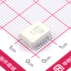
ACPL-M43T
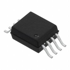
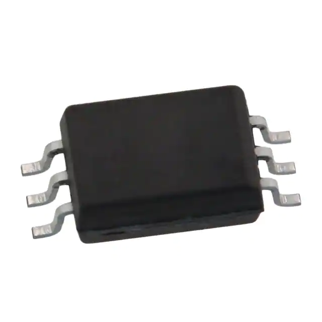
Automotive Wide Operating Temperature 1MBd Digital Optocoupler in a 5-Pin Surface Mount Plastic Package
Data Sheet
Lead (Pb) Free RoHS 6 fully compliant
RoHS 6 fully compliant options available; -xxxE denotes a lead-free product
Description
The ACPL-M43T is a single channel, high temperature, high CMR, high speed digital optocoupler in a five lead miniature footprint specifically used in the automotive applications. The SO-5 JEDEC registered (MO-155) package outline does not require “through holes” in a PCB. This package occupies approximately one-fourth the footprint area of the standard dual-in-line package. The lead profile is designed to be compatible with standard surface mount processes. This digital optocoupler uses an insulating layer between the light emitting diode and an integrated photon detector to provide electrical insulation between input and output. Separate connections for the photodiode bias and output transistor collector increase the speed up to a hundred times over that of a conventional photo-transistor coupler by reducing the base-collector capacitance. The ACPL-M43T has an increased common mode transient immunity of 30kV/µs minimum at VCM = 1500V over extended temperature range.
Features
• High Temperature and Reliability IPM Driver for Automotive Application. • 30 kV/µs High Common-Mode Rejection at VCM = 1500 V (typ) • Compact, Auto-Insertable SO5 Packages • Wide Temperature Range: -40°C ~ 125°C • High Speed: 1MBd (Typ) • Low LED Drive Current: 10mA (typ) • Low Propagation Delay: 300ns (typ) • Worldwide Safety Approval: − UL1577 recognized, 3750Vrms/1min − CSA Approved − IEC/EN/DIN EN 60747-5-2 Approved
Applications
• Automotive IPM Driver for DC-DC converters and motor inverters • CANBus Communications Interface • High Temperature Digital/Analog Signal Isolation • Power Transistor Isolation
Functional Diagram
I CC 6 VCC
ANODE
+ 1 VF 3
IF
IO
5
CATHODE
VO
SHIELD Note: The connection of a 0.1 µF bypass capacitor between pins 4 and 6 is recommended.
4
GND
Truth Table
LED ON OFF
Vo LOW HIGH
CAUTION: It is advised that normal static precautions be taken in handling and assembly of this component to prevent damage and/or degradation which may be induced by ESD.
�Ordering Information
Option Part number
ACPL-M43T
RoHS Compliant
-000E -500E
Non RoHS Compliant
No option -500
Package
SO-5
Surface Mount
X X
Gull Wing
Tape & Reel
X
UL 5000 Vrms / 1 Minute IEC/EN/DIN rating EN 60747-5-2 Quantity
100 per tube 1500 per reel
To order, choose a part number from the part number column and combine with the desired option from the option column to form an order entry. Example 1: ACPL-M43T-500E to order product of Mini-flat Surface Mount 5-pin package in Tape and Reel packaging with RoHS compliant. Example 2: ACPL-M43T to order product of Mini-flat Surface Mount 5-pin package in tube packaging and non RoHS compliant. Option datasheets are available. Contact your Avago sales representative or authorized distributor for information. Remarks: The notation ‘#XXX’ is used for existing products, while (new) products launched since 15th July 2001 and RoHS compliant option will use ‘-XXXE‘.
Package Outline Drawings ACPL-M43T Small Outline SO-5 Package (JEDEC MO-155)
Extended Datecode for lot tracking
ANODE 7.0 ± 0.2 (0.276 ± 0.008) CATHODE 3 1 6 5 4 V CC V OUT GND
4.4 ± 0.1 (0.173 ± 0.004)
M43T YWW EE
0.4 ± 0.05 (0.016 ± 0.002) 3.6 ± 0.1* (0.142 ± 0.004) 2.5 ± 0.1 (0.098 ± 0.004) 0.102 ± 0.102 (0.004 ± 0.004) 0.20 ± 0.025 (0.008 ± 0.001) 7 MAX. 1.27 BSC (0.050) 0.71 MIN. (0.028) MAX. LEAD COPLANARITY = 0.102 (0.004)
o
DIMENSIONS IN MILLIMETERS (INCHES) * MAXIMUM MOLD FLASH ON EACH SIDE IS 0.15 mm (0.006) NOTE: FLOATING LEAD PROTRUSION IS 0.15 mm (6 mils) MAX.
�
�Land Pattern Recommendation
4.4 (0.17)
2.5 (0.10)
1.3 (0.05)
2.0 (0.080) 8.27 (0.325)
0.64 (0.025)
DIMENSIONS IN MILLIMETERS AND (INCHES)
Solder Reflow Temperature Profile
300 PREHEATING RATE 3 °C + 1 °C/- 0.5 °C/SEC. REFLOW HEATING RATE 2.5°C ± 0.5 °C/SEC. PEAK TEMP. 245 °C PEAK TEMP. 240 °C
TEMPERATURE ( °C)
200 160 °C 150 °C 140 °C
2.5 °C ± 0.5 °C/SEC. 30 SEC. 3°C + 1 °C/- 0.5 °C 30 SEC.
PEAK TEMP. 230 °C
SOLDERING TIME 200 °C
100 PREHEATING TIME 150 °C, 90 + 30 SEC. ROOM TEMPERATURE 0 0 50 100 TIME (SECONDS) 150 200 50 SEC. TIGHT TYPICAL LOOSE 250
Note: Non-halide flux should be used.
Recommended Pb-Free IR Profile
tp Tp TL 260 +0/-5 °C 217 °C RAMP-UP 3 ° C/SEC. MAX. 150 - 200 °C TIME WITHIN 5°C of ACTUAL PEAK TEMPERATURE 20-40 SEC.
TEMPERATURE
T smax
RAMP-DOWN 6 °C/SEC. MAX.
T smin ts PREHEAT 60 to 180 SEC. 25 tL 60 to 150 SEC.
t 25 °C to PEAK
TIME NO TES: THE TIME FROM 25°C to PEAK TEMPERATURE = 8 MINUTES MAX. T smax = 200 °C, Tsmin = 150 °C
Note: Non-halide flux should be used.
�
�Regulatory Information
The ACPL-M43T is approved by the following organizations: UL Approved under UL 1577, component recognition program up to VISO = 3750 VRMS expected prior to product release.. CSA Approved under CSA Component Acceptance Notice #5. IEC/EN/DIN EN 60747-5-2 Insulation Characteristics* Description
Installation classification per DIN VDE 0110/1.89, Table 1 for rated mains voltage ≤ 150 Vrms for rated mains voltage ≤ 300 Vrms for rated mains voltage ≤ 600 Vrms Climatic Classification Pollution Degree (DIN VDE 0110/1.89) Maximum Working Insulation Voltage Input to Output Test Voltage, Method b* VIORM x 1.875=VPR, 100% Production Test with tm=1 sec, Partial discharge < 5 pC Input to Output Test Voltage, Method a* VIORM x 1.5=VPR, Type and Sample Test, tm=60 sec, Partial discharge < 5 pC Highest Allowable Overvoltage (Transient Overvoltage tini = 10 sec) Safety-limiting values – maximum values allowed in the event of a failure. Case Temperature Input Current Output Power Insulation Resistance at TS, VIO = 500 V
*
IEC/EN/DIN EN 60747-5-2 Approved under: IEC 60747-5-2:1997 + A1 EN 60747-5-2:2001 + A1 DIN EN 60747-5-2 (VDE 0884 Teil 2)
Symbol
Characteristic
I – IV I – III I – II 55/125/21 2
Unit
VIORM VPR VPR VIOTM TS IS, INPUT PS, OUTPUT RS
567 1063 851 6000 175 230 600 >109
Vpeak Vpeak Vpeak Vpeak °C mA mW W
Refer to the optocoupler section of the Isolation and Control Components Designer’s Catalog, under Product Safety Regulations section, (IEC/EN/DIN EN 60747-5-2) for a detailed description of Method a and Method b partial discharge test profiles.
Insulation and Safety Related Specifications
Parameter
Minimum External Air Gap (Clearance) Minimum External Tracking (Creepage) Minimum Internal Plastic Gap (Internal Clearance) Tracking Resistance (Comparative Tracking Index) Isolation Group (DIN VDE0109) CTI
Symbol
L(101) L(102)
ACPL-M43T
≥5 ≥5 0.08
Units
mm mm mm
Conditions
Measured from input terminals to output terminals, shortest distance through air. Measured from input terminals to output terminals, shortest distance path along body. Through insulation distance conductor to conductor, usually the straight line distance thickness between the emitter and detector. DIN IEC 112/VDE 0303 Part 1
175
V
IIIa
Material Group (DIN VDE 0109)
�
�Absolute Maximum Ratings
Parameter
Storage Temperature Operating Temperature Lead Soldering Cycle Average Forward Input Current Peak Forward Input Current (50% duty cycle, 1ms pulse width) Peak Transient Input Current ( 2.0 V). Common mode transient immunity in a Logic Low level is the maximum tolerable (negative) dVCM/dt on the falling edge of the common mode pulse signal, VCM to assure that the output will remain in a Logic Low state (i.e., VO < 0.8 V). 9. The 1.9 kW load represents 1 TTL unit load of 1.6 mA and the 5.6 kW pull-up resistor. 10. The frequency at which the ac output voltage is 3 dB below its mid-frequency value. 11. Use of a 0.1 µF bypass capacitor connected between pins 4 and 6 is recommended. 12. Pulse Width Distortion (PWD) is defined as |tPHL - tPLH| for any given device. 13. The difference between tPLH and tPHL between any two parts under the same test condition.
�
�30 25
NORMALIZED CURRENT TRANSFER RATIO
VCC = 5.0V TA = 25oC
40mA 35mA 30mA 25mA 20mA 15mA
2.0 1.8 1.6 1.4 1.2 1.0 0.8 0.6 0.4 0.2 0 0.1 1 10 I F - INPUT CURRENT - mA 100 Normalized I F = 10mA V O = 0.4V V CC = 5V T A = 25 o C
IO - OUTPUT CURRENT - mA
20 15
10mA 10 IF=5mA 5 0
0
10 V O - OUTPUT VOLTAGE - V
20
Figure 1. DC and Pulsed Transfer Characteristics.
Figure 2. Current Transfer Ratio vs Input Current
NORMALIZED CURRENT TRANSFER RATIO
100.00
IF - FORWARD CURRENT - mA
1.1 1.0 0.9 Normalized 0.8 0.7 0.6 IF = 10mA, VO = 0.4V VCC = 5.0V T A = 25 C -60 -20 20 60
o o
10.00
TA = 25oC
1.00
0.10
0.01
1.2
1.3
1.4 V F - Forward Voltage - VOLTS
1.5
1.6
100
140
TA - TEMPERATURE - C
Figure 3. Input Current vs Forward Voltage
Figure 4. Current Transfer Ratio vs Temperature
800 IF =10mA, VCC =5.0V
1 tp - Propogation Delay - us 0.8 0.6 0.4 0.2
V CC = 5.0 V, T A = 25 C C L = 15pF, RL = 1.9 kΩ V THHL = 1.5V V THLH = 2.0V, 50% Duty Cycle I F = 10mA TPLH
o
T P - PROPOGATION DELAY - ns
600 TpLH 400 TpHL
R L =1.9k
200
TPHL
0 -60 -20 20 60
o
0
100 C
140
0
2
4
6
8
10
T A - TEMPERATURE -
R L - Load Resistance - kohm
Figure 5. Propagation Delay vs Temperature
Figure 6. Propagation Delay Time vs Load Resistance
�I OH - LOGIC HIGH OUTPUT CURRENT - nA
1000 100 10 1 0.1 0.01 -60 -20 20 60
o
IF = 0mA V O = VCC = 5.0V
100 C
140
T A - TEMPERATURE -
Figure 7. Logic High Output Current vs Temperature.
IF 0 VO 1.5 V 1.5 V VOL t PHL t PLH 5V
PULSE GEN. Z O = 50Ω tr = 5 ns 10% DUTY CYCLE 1/f 100 µs
IF 1 6 RL 5 0.1µF 3 100 Ω VO +5 V
I F MONITOR
4 C L = 15 pF
Figure 8. Switching Test Circuit
tr , t f = 16 ns VCM 0V 10 V 10% tr 90% 90% 10% tf
IF B A VFF 3 5 0.1µF 4 VCC 1 6 RL VO
VO SWITCH AT A: IF = 0 mA VO SWITCH AT B: I F = 1.6 mA
5V
VOL
+
VCM
-
PULSE GEN.
Figure 9. Test Circuit for Transient Immunity and Typical Waveforms.
For product information and a complete list of distributors, please go to our web site:
www.avagotech.com
Avago, Avago Technologies, and the A logo are trademarks of Avago Technologies, Limited in the United States and other countries. Data subject to change. Copyright © 2008 Avago Technologies Limited. All rights reserved. Obsoletes AV01-0458EN AV02-0565EN - February 1, 2008
�
很抱歉,暂时无法提供与“ACPL-M43T”相匹配的价格&库存,您可以联系我们找货
免费人工找货- 国内价格
- 1+26.70299
- 10+25.71399
- 100+22.74699
- 500+22.15359
- 国内价格
- 1+12.35655
- 10+11.8989
- 100+10.52595
- 500+10.25136
- 国内价格
- 1+13.5
- 10+13
- 100+11.5
- 500+11.2
- 国内价格
- 1+10.9836
- 10+10.5768
- 100+9.3564
- 500+9.11232
- 国内价格
- 1+35.1
- 10+33.8
- 100+29.9
- 500+29.12
- 国内价格
- 1+11.7
- 10+10.8
- 30+10.62
- 国内价格
- 1+44.28
- 10+42.64
- 100+37.72
- 500+36.736
- 国内价格
- 1+11.8935
- 10+11.453
- 100+10.1315
- 500+9.8672