ACPL-M75L
Single-channel High Speed 15 MBd CMOS optocoupler
with Glitch-Free Power-Up Feature
Data Sheet
Lead (Pb) Free
RoHS 6 fully
compliant
RoHS 6 fully compliant options available;
-xxxE denotes a lead-free product
Description
Features
The ACPL-M75L (single-channel) is 15 MBd CMOS optocouplers in SOIC-5 package. The optocouplers utilize the
latest CMOS IC technology to achieve outstanding performance with very low power consumption. Basic building blocks of ACPL-M75L are high speed LEDs and CMOS
detector ICs. Each detector incorporates an integrated
photodiode, a high speed transimpedance amplifier, and
a voltage comparator with an output driver.
• +3.3V and +5 V CMOS compatibility
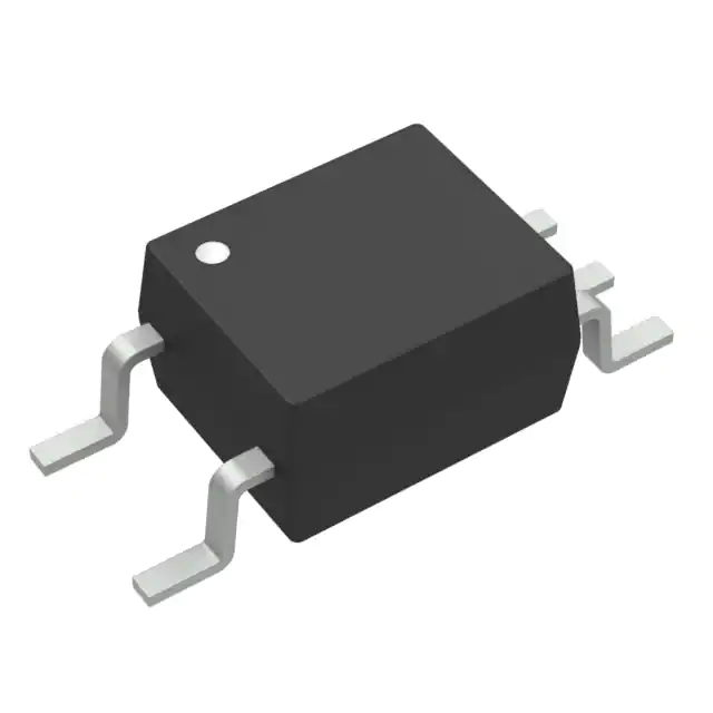
Component Image
• 25ns max. pulse width distortion
• 55ns max. propagation delay
• 40ns max. propagation delay skew
• High speed: 15 MBd min
• 10 kV/µs minimum common mode rejection
• –40 to 105°C temperature range
• Glitch-Free Power-UP Feature
• Safety and regulatory approvals:
ACPL-M75L
6 Vdd
Anode 1
5 Vo
- UL recognized: 3750 V rms for 1 min. per UL 1577
- CSA component acceptance Notice #5
- IEC/EN/DIN EN 60747-5-5 approved Option 060
Applications
• Digital field bus isolation:
Cathode 3
4 Gnd
SHIELD
A 0.1uF bypass capacitor must be connected between pins 4 and 6.
TRUTH TABLE
LED
OFF
ON
VO, OUTPUT
H
- RS485, RS232, CANbus
• Multiplexed data transmission
• Computer peripheral interface
• Microprocessor system interface
• DC/DC converter
• Servo Motor
L
CAUTION: It is advised that normal static precautions be taken in handling and assembly
of this component to prevent damage and/or degradation which may be induced by ESD.
�Ordering Information
ACPL-M75L will be UL Recognized with 3750 Vrms for 1 minute per UL1577.
Option
Part number
RoHS Compliant
Package
Surface Mount
-000E
-500E
ACPL-M75L
-060E
IEC/EN/DIN EN
60747-5-5
Tape& Reel
X
100 per tube
X
SO-5
X
1500 per reel
X
-560E
Quantity
X
X
X
100 per tube
X
1500 per reel
To order, choose a part number from the part number column and combine with the desired option from the option
column to form an order entry.
Example 1:
ACPL-M75L-500E to order product of Small Outline SO-5 package in Tape and Reel packaging in RoHS compliant.
Example 2:
ACPL-M75L-000E to order product of Small Outline SO-5 package in tube packaging and in RoHS compliant.
Option datasheets are available. Contact your Avago sales representative or authorized distributor for information.
Package Dimensions
ACPL-M75L (JEDEC MO-155 Package)
LAND PATTERN RECOMMENDATION
0.33
(0.013)
Device
Part Number
4.4 ± 0.1
(0.173 ± 0.004)
Lead Free
NNNN Z
• YYWW
EEE
Test Rating
Code
0.64
(0.025)
7.0 ± 0.2
(0.276 ± 0.008)
Date Code
4.39
(0.17)
8.26
(0.325)
Lot ID
Pin 1 Dot
1.80
(0.071)
0.4 ± 0.05
(0.016 ± 0.002)
2.54
(0.10)
3.6 ± 0.1*
(0.142 ± 0.004)
2.5 ± 0.1
(0.098 ± 0.004)
0.102 ± 0.102
(0.004 ± 0.004)
1.27 BSC
(0.050)
Dimensions in millimeters (inches).
Note: Foating Lead Protrusion is 0.15 mm (6 mils) max.
* Maximum Mold flash on each side is 0.15 mm (0.006).
2
1.27
(0.05)
0.15 ± 0.025
(0.006 ± 0.001)
7° MAX.
0.71 MIN
(0.028)
MAX. LEAD COPLANARITY
= 0.102 (0.004)
�Regulatory Information
The ACPL-M75L has been approved by the following organizations:
UL
CSA
IEC/EN/DIN EN 60747-5-5
Recognized under UL 1577, component recognition program, File E55361.
Approved under CSA Component Acceptance Notice #5, File CA88324.
Insulation and Safety Related Specifications
Parameter
Symbol
Value
Units
Conditions
Minimum External Air
Gap (Clearance)
L(I01)
≥5
mm
Measured from input terminals to output terminals,
shortest distance through air.
Minimum External
Tracking (Creepage)
L(I02)
≥5
mm
Measured from input terminals to output terminals,
shortest distance path along body.
Minimum Internal Plastic
Gap (Internal Clearance)
0.08
mm
Insulation thickness between emitter and detector;
also known as distance through insulation.
Tracking Resistance
CTI
(Comparative Tracking Index)
≥175
Volts
DIN IEC 112/VDE 0303 Part 1
Isolation Group
IIIa
Material Group (DIN VDE 0110, 1/89, Table 1)
All Avago Technologies data sheets report the creepage and clearance inherent to the optocoupler component itself.
These dimensions are needed as a starting point for the equipment designer when determining the circuit insulation
requirements. However, once mounted on a printed circuit board, minimum creepage and clearance requirements must
be met as specified for individual equipment standards. For creepage, the shortest distance path along the surface of
a printed circuit board between the solder fillets of the input and output leads must be considered. There are recommended techniques such as grooves and ribs which may be used on a printed circuit board to achieve desired creepage
and clearances. Creepage and clearance distances will also change depending on factors such as pollution degree and
insulation level.
IEC/EN/DIN EN 60747-5-5 Insulation Related Characteristics (Option 060)
Description
Symbol
option 060
Installation classification per DIN VDE 0110/1.89, Table 1
for rated mains voltage ≤150 V rms
for rated mains voltage ≤300 V rms
I-IV
I-III
Climatic Classification
55/105/21
Pollution Degree (DIN VDE 0110/1.89)
2
Units
Maximum Working Insulation Voltage
VIORM
567
VPEAK
Input to Output Test Voltage, Method b†
VIORM x 1.875 = VPR, 100% Production
Test with tm = 1 sec, Partial Discharge < 5 pC
VPR
1063
VPEAK
Input to Output Test Voltage, Method a†
VIORM x 1.6 = VPR, Type and Sample Test,
tm = 10 sec, Partial Discharge < 5 pC
VPR
907
VPEAK
Highest Allowable Overvoltage†
(Transient Overvoltage, tini = 60 sec)
VIOTM
6000
VPEAK
Safety Limiting Values (Maximum values allowed in the event of a failure,
also see Thermal Derating curve, Figure 11.)
Case Temperature
Input Current
Output Power
Ts
Is, INPUT
Ps,OUTPUT
150
150
600
°C
mA
mW
Insulation Resistance at TS, V10 = 500 V
RIO
≥109
Ω
3
�Absolute Maximum Ratings
Parameter
Symbol
Min.
Max.
Units
Storage Temperature
TS
–55
+125
°C
Ambient Operating Temperature
TA
–40
+105
°C
Supply Voltages
VDD
0
6.0
Volts
Output Voltage
VO
–0.5
VDD +0.5
Volts
Average Forward Input Current
IF
-
10.0
mA
Average Output Current
Io
-
10.0
mA
Lead Solder Temperature
260°C for 10 sec., 1.6 mm below seating plane
Solder Reflow Temperature Profile
See Solder Reflow Temperature Profile Section
Recommended Operating Conditions
Parameter
Symbol
Min.
Max.
Units
Ambient Operating Temperature
TA
–40
+105
°C
Supply Voltages
VDD
4.5
5.5
V
3.0
3.6
V
Input Current (ON)
IF
4
8
mA
Forward Input Voltage (OFF)
VF(OFF)
0
0.8
V
Supply Voltage Slew Rate[1]
SR
0.5
500
V/ms
Electrical Specifications
Over recommended temperature (TA = –40°C to +105°C), 3.0V ≤ VDD ≤ 3.6V and 4.5 V ≤ VDD ≤ 5.5 V.
All typical specifications are at TA=+25°C, VDD= +3.3V.
Parameter
Symbol
Min.
Typ.
Max.
Units
Test Conditions
Input Forward Voltage
VF
1.3
1.5
1.8
V
IF = 6mA
Input Reverse
Breakdown Voltage
BVR
5.0
V
IR = 10 µA
Logic High Output Voltage
VOH
VDD -1
VDD -0.3
V
IF = 0, IO = -4 mA, VDD=3.3V
VDD -1
VDD -0.2
V
IF = 0, IO = -4 mA, VDD=5V
Logic Low Output Voltage
VOL
0.2
0.8
V
IF = 6mA, IO = 4mA, VDD=3.3V
0.35
0.8
V
IF = 6mA, IO = 4mA, VDD=5V
Input Threshold Current
ITH
1
3
mA
IOL = 20 µA
Logic Low Output Supply Current
IDDL
4.5
6.5
mA
IF = 6 mA
Logic High Output Supply Current
IDDH
4
6
mA
IF = 0
4
�Switching Specifications
Over recommended temperature (TA = –40°C to +105°C), 3.0V ≤ VDD ≤ 3.6V and 4.5 V ≤ VDD ≤ 5.5 V.
All typical specifications are at TA=+25°C, VDD = +3.3V.
Parameter
Symbol
Propagation Delay Time
to Logic Low Output[2]
Typ.
Max.
Units
Test Conditions
tPHL
25
55
ns
IF = 6mA, CL= 15pF
CMOS Signal Levels
Propagation Delay Time
to Logic High Output[2]
tPLH
21
55
ns
IF = 6mA, CL= 15pF,
CMOS Signal Levels
Pulse Width
tPW
66.7
Pulse Width Distortion[3]
|PWD |
0
Propagation Delay Skew[4]
tPSK
Output Rise Time
(10% – 90%)
tR
Output Fall Time
(90% - 10%)
tF
Common Mode Transient
Immunity at Logic High Output[5]
| CMH |
Common Mode Transient
Immunity at Logic Low Output[6]
| CML |
Min.
ns
4
25
ns
IF = 6mA, CL= 15pF,
CMOS Signal Levels
40
ns
IF = 6mA, CL= 15pF
CMOS Signal Levels
3.5
ns
IF = 6mA, CL= 15pF
CMOS Signal Levels
3.5
ns
IF = 6mA, CL= 15pF
CMOS Signal Levels
10
15
kV/µs
VCM = 1000 V, TA = 25°C,
IF = 0 mA (Figure 18)
30
35
kV/µs
Using Avago’s Application Circuit
(Figure 13)
10
15
kV/µs
VCM = 1000 V, TA = 25°C,
IF = 6 mA (Figure 18)
30
35
kV/µs
Using Avago’s Application Circuit
(Figure 13)
Min.
Typ.
Max.
Units
Test Conditions
1.0
µA
45% RH, t = 5 s
VI-O = 3 kV DC,
TA = 25°C
Vrms
RH ≤ 50%, t = 1 min.,
TA = 25°C
Package Characteristics
All Typical at TA = 25°C.
Parameter
Symbol
Input-Output Insulation
II-O
Input-Output Momentary
Withstand Voltage
VISO
Input-Output Resistance
R I-O
10 12
W
V I-O = 500 V dc
Input-Output Capacitance
C I-O
0.6
pF
f = 1 MHz, TA = 25°C
3750
Notes:
1. Slew rate of supply voltage ramping is recommended to ensure no glitch more than 1V to appear at the output pin.
2. tPHL propagation delay is measured from the 50% VDD level on the rising edge of the input pulse to the 50% VDD level of the falling edge of the VO
signal. tPLH propagation delay is measured from the 50% VDD level on the falling edge of the input pulse to the 50% VDD level of the rising edge of
the VO signal.
3. PWD is defined as |tPHL - tPLH|.
4. tPSK is equal to the magnitude of the worst case difference in tPHL and/or tPLH that will be seen between units at any given temperature within the
recommended operating conditions.
5. CMH is the maximum tolerable rate of rise of the common mode voltage to assure that the output will remain in a high logic state.
6. CML is the maximum tolerable rate of fall of the common mode voltage to assure that the output will remain in a low logic state.
5
�10
1.600
1
Ith -INPUT THRESHOLD CURRENT-mA
IF -FORWARD CURRENT-mA
IF
TA=25°C
VF
0.1
0.01
1.2
1.3
1.4
1.5
V F -FORWARD VOLTAGE-V
4
3
2
VDD=5V
VDD=3.3V
-40
-20
0.800
0
20
40
60
T A -TEMPERATURE-o C
80
100
Figure 3. Typical logic high O/P supply current vs. temperature.
0.200
0
20
40
60
TA -TEMPERATURE- o C
80
100
120
6
5
4
3
2
VDD=5.0V
VDD=3.3V
1
0
-40
-20
0
20
40
60
T A -TEMPERATURE-oC
80
100
35
tp – PROPAGATION DELAY;
PWD-PULSE WIDTH DISTORTION – ns
tp – PROPAGATION DELAY;
PWD-PULSE WIDTH DISTORTION – ns
-20
Figure 4. Typical logic low O/P supply current vs. temperature.
TPHL
30
25
20
TPLH
15
10
PWD
5
VDD=5V
Ta=25°C
4
5
6
7
IF – PULSE INPUT CURRENT – mA
8
Figure 5. Typical switching speed vs. pulse input current at 5V supply voltage.
6
5V
3.3V
0.400
35
0
I oL =20uA
0.600
IDDL-LOGIC LOW OUTPUT SUPPLY CURRENT-mA
IDDH-LOGIC HIGH OUTPUT SUPPLY CURRENT -mA
5
0
1.000
Figure 2. Typical input threshold current vs. temperature.
6
1
1.200
0.000
-40
1.6
Figure 1. Typical input diode forward characteristic.
1.400
TPHL
30
25
20
TPLH
15
10
PWD
5
0
VDD=3.3V
Ta=25°C
4
5
6
7
IF – PULSE INPUT CURRENT – mA
Figure 6. Typical switching speed vs. pulse input current at 3.3V supply
voltage.
8
�1.8
1.6
1.3
2
Gnd1
1.2
1
- 40
4
VO
3
Gnd2
C = 0.01 uF to 0.1uF
-20
0
20
40
60
TA - TEMPERATURE - oC
80
100
Figure 8. Recommended printed circuit board layout
Figure 7. Typical VF vs. temperature.
Application Information
Bypassing and PC Board Layout
The ACPL-M75L optocoupler is extremely easy to use.
ACPL-M75L provides CMOS logic output due to the highspeed CMOS IC technology used.
The external components required for proper operation
are the input limiting resistor and the output bypass capacitor. Capacitor values should be between 0.01 µF and
0.1 µF.
For each capacitor, the total lead length between both
ends of the capacitor and the power-supply pins should
not exceed 20 mm.
Propagation Delay, Pulse-Width Distortion and Propagation Delay Skew
Propagation delay is a figure of merit which describes how
quickly a logic signal propagates through a system. The
propagation delay from low to high (tPLH) is the amount
of time required for an input signal to propagate to the
output, causing the output to change from low to high.
Similarly, the propagation delay from high to low (tPHL) is
the amount of time required for the input signal to propagate to the output, causing the output to change from
high to low (see Figure 9).
DATA
50%
INPUTS
2.5 V,
CMOS
VO
CLOCK
tPSK
IF
50%
DATA
OUTPUTS
VO
Figure 9. Propagation delay and skew waveform
7
V DD2
C
1.4
1.1
IF
5
1
Iin
1.5
XXX
YWW
VF - FORWARD VOLTAGE - C
1.7
2.5 V,
CMOS
tPSK
CLOCK
tPSK
Figure 10. Parallel data transmission example
�Pulse-width distortion (PWD) results when tPLH and tPHL
differ in value. PWD is defined as the difference between
tPLH and tPHL and often PWD determines the maximum
data rate capability of a transmission system. PWD can be
expressed in percent by dividing the PWD (in ns) by the
minimum pulse width (in ns) being transmitted. Typically,
PWD on the order of 20-30% of the minimum pulse width
is tolerable; the exact figure depends on the particular application (RS232, RS422, T-1, etc.).
Propagation delay skew, tPSK, is an important parameter
to consider in parallel data applications where synchronization of signals on parallel data lines is a concern.
If the parallel data is being sent through a group of optocouplers, differences in propagation delays will cause the
data to arrive at the outputs of the optocouplers at different times. If this difference in propagation delays is large
enough, it will determine the maximum rate at which parallel data can be sent through the optocouplers.
Propagation delay skew is defined as the difference between the minimum and maximum propagation delays,
either tPLH or tPHL, for any given group of optocouplers
which are operating under the same conditions (i.e., the
same supply voltage, output load, and operating temperature). As illustrated in Figure 10, if the inputs of a group of
optocouplers are switched either ON or OFF at the same
time, tPSK is the difference between the shortest propagation delay, either tPLH or tPHL, and the longest propagation
delay, either tPLH or tPHL. As mentioned earlier, tPSK can determine the maximum parallel data transmission rate.
Figure 10 is the timing diagram of a typical parallel data
application with both the clock and the data lines being
sent through optocouplers. The figure shows data and
clock signals at the inputs and outputs of the optocouplers. To obtain the maximum data transmission rate, both
35
edges of the clock signal are being used to clock the data;
if only one edge were used, the clock signal would need
to be twice as fast.
Propagation delay skew represents the uncertainty of
where an edge might be after being sent through an optocoupler. Figure 10 shows that there will be uncertainty in
both the data and the clock lines. It is important that these
two areas of uncertainty not overlap, otherwise the clock
signal might arrive before all of the data outputs have
settled, or some of the data outputs may start to change
before the clock signal has arrived.
From these considerations, the absolute minimum pulse
width that can be sent through optocouplers in a parallel
application is twice tPSK. A cautious design should use a
slightly longer pulse width to ensure that any additional
uncertainty in the rest of the circuit does not cause a
problem.
The tPSK specified optocouplers offer the advantages of
guaranteed specifications for propagation delays, pulsewidth distortion and propagation delay skew over the recommended temperature, and power supply ranges.
C peak
R drv = 50 Ω
Vin
+
0.1 µF
-
GND 1
Figure 11. Connection of peaking capacitor (Cpeak) in parallel of the input
limiting resistor (Rlimit) to improve speed performance
t PHL
35
t PLH
25
With peaking cap
Without peaking cap
t PLH
20
t PLH
30
25
t PLH
20
15
15
t PHL
10
5
0
0
-40
-20
0
20
40
60
80
100
With peaking cap
Without peaking cap
t PHL
10
|PWD|
5
(i) VDD=5V, Cpeak=100pF, Rlimit=530Ω
|PWD|
-40
-20
0
20
(ii) VDD=3.3V, Cpeak=100pF, Rlimit=250Ω
Figure 12. Improvement of tp and PWD with added 100pF peaking capacitor in parallel of input limiting resistor.
8
VO
GND 2
SHIELD
SHIEL
40
t PHL
30
VDD2
R limit
40
60
80
100
�Powering Sequence
VDD needs to achieve a minimum level of 3V before powering up the output connecting component.
Input Limiting Resistors
ACPL-M75L is direct current driven (Figure 8), and thus
eliminate the need for input power supply. To limit the
amount of current flowing through the LED, it is recommended that a 530ohm resistor is connected in series with
anode of LED (i.e. Pin 1 for ACPL-M75L) at 5V input signal.
At 3.3V input signal, it is recommended to connect 250Ω
resistor in series with anode of LED. The recommended
limiting resistors is based on the assumption that the driver output impedence is 50Ω (as shown in Figure 11).
Speed Improvement
A peaking capacitor can be placed across the input current limit resistor (Figure 11) to achieve enhanced speed
performance. The value of the peaking cap is dependent
to the rise and fall time of the input signal and supply voltages and LED input driving current (If ). Figure 12 shows
significant improvement of propagation delay and pulse
with distortion with added peak capacitor at driving current of 6mA for both 3.3V and 5V power supply.
Common Mode Rejection for ACPL-M75L
Figure 13 shows the recommended drive circuit for the
ACPL-M75L for optimal common-mode rejection performance. Two LED-current setting resistors are used instead
of one. This is to balance the common mode impedance
at LED anode and cathode. Common-mode transients can
capacitively couple from the LED anode (or cathode) to
the output-side ground causing current to be shunted
away from the LED (which can be bad if the LED is on) or
conversely cause current to be injected into the LED (bad
if the LED is meant to be off ). Figure14 shows the parasitic
capacitances which exists between LED anode/cathode
and output ground (CLA and CLC). Also shown in Figure 14
on the input side is an AC-equivalent circuit.
Table 1 indicates the directions of ILP and ILN flow depending on the direction of the common-mode transient. For
transients occurring when the LED is on, common-mode
rejection (CML, since the output is in the “low” state) depends upon the amount of LED current drive (IF). For conditions where IF is close to the switching threshold (ITH),
CML also depends on the extent which ILP and ILN balance
each other. In other words, any condition where commonmode transients cause a momentary decrease in IF (i.e.
when dVCM/dt>0 and |IFP| > |IFN|, referring to Table 1) will
cause common-mode failure for transients which are fast
enough.
Likewise for common-mode transients which occur when
the LED is off (i.e. CMH, since the output is “high”), if an imbalance between ILP and ILN results in a transient IF equal
to or greater than the switching threshold of the optocoupler, the transient “signal” may cause the output to spike
below 2V (which constitutes a CMH failure).
By using the recommended circuit in Figure 13, good CMR
can be achieved. The resistors recommended in Figure 13
include both the output impedence of the logic driver circuit and the external limiting resistor. The balanced ILEDsetting resistors help equalize the common mode voltage
change at anode and cathode to reduce the amount by
which ILED is modulated from transient coupling through
CLA and CLC.
Table 1. Effects of Common Mode Pulse Direction on Transient ILED
If |ILP| < |ILN|,
LED IF Current
Is Momentarily:
If |ILP| > |ILN|,
LED IF Current
Is Momentarily:
If dVCM/dt Is:
then ILP Flows:
and ILN Flows:
positive (>0)
away from LED
anode through CLA
away from LED
cathode through CLC
increased
decreased
negative (


 工商网监
湘ICP备2023018690号
工商网监
湘ICP备2023018690号
