AEDR-8300 Series Encoders
Reflective Surface Mount Optical Encoder
Data Sheet
Description
Features
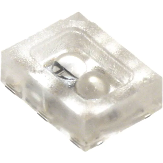
The AEDR-8300 series is the smallest optical encoder
employing reflective technology for motion control
purposes. The encoder houses an LED light source and
a photo-detecting circuitry in a single package.
• Reflective technology
The AEDS-8300 series offers options of either single
channel or two-channel quadrature digital outputs.
Being TTL compatible, the outputs of the AEDR-8300
series can be interfaced directly with most of the signal
processing circuitries. Hence the encoder provides great
design-in flexibility and easy integration into existing
systems. The AEDR-8300 series is available in four resolutions, namely 36, 75, 150 and 180 lines per inch (LPI)
(1.42, 2.95, 5.91 and 7.09 lines per mm respectively).
This range of resolutions caters for different design and
application needs.
• Two channel quadrature outputs for direction sensing
Applications
The AEDR-8300 series provides motion sensing at a
competitive cost, making it ideal for high volume applications. Its small size and surface mount package make
it ideal for printers, copiers, card readers and many consumer products, particularly where space and weigh are
design constraint.
Note: All specifications are subject to change without prior notification.
• Surface mount small outline leadless package
• Single channel incremental output
• TTL compatible output
• Single 5V supply
• -20oC to 85oC absolute operating temperature
• Encoding resolution options:
36, 75, 150, 180 (lines/inch) or 1.42, 2.95, 5.91, 7.09
(lines/mm)
�Theory of Operation
Definitions
The AEDR-8300 series combines an emitter and a detector in a single surface mount leadless package. When
used with a codewheel or linear codestrip, the encoder
translates rotary or linear motion into digital outputs.
As seen in the block diagram, the AEDR-8300 consists
of three major components: a light emitting diode (LED)
light source, a detector IC consisting photodiodes and
lens to focus light beam from the emitter as well as light
falling on the detector.
State Width (S): The number of electrical degrees between a transition in Channel A and the neighboring
transition in Channel B. There are 4 states per cycle,
each nominally 90oe.
The operation of the encoder is based on the principle
of optics where the detector photodiodes sense the absence and presence of light. In this case, the rotary/linear motion of an object being monitored is converted
to equivalent light pattern via the use of codewheel/
codestrip. As shown in the diagram below, the reflective
area (window) of the codewheel (or codestrip) reflects
light back to the photodetector IC, whereas no light is
reflected by the non-reflective area (bar). An alternating
light and dark patterns corresponding to the window
and bar fall on the photodiodes as the codewheel rotates. The moving light pattern is exploited by the detector circuitry to produce digital outputs representing
the rotation of the codewheel. When the codewheel is
coupled to a motor, the encoder outputs is then a direct
representation of the motor rotation. The same concept
applies to the use of a codestrip to detect linear motion.
VLED
R
VCC
CH B
SIGNAL
PROCESSING
CIRCUITRY
GND
Figure 1. Block Diagram of AEDR-8300.
AEDR-8300 block diag
�
Phase (φ): The number of electrical degrees between
the center of high state of Channel A and the center of
high state of Channel B. Nominally 90oe.
Phase Error (∆φ): The deviation of phase, in electrical
degree, from its ideal value of 90oe.
Pulse Width (P): The duration of high state of the output, in electrical degree, within one cycle. Nominally
180oe or half a cycle.
Pulse Width Error (∆P): The deviation of pulse width, in
electrical degree, from its ideal value of 180oe.
Count (N): The number of window and bar pair per revolution (CPR) of codewheel. For linear codestrip, defined
as the number of window and bar pair per unit length
(lines per inch [LPI] or lines per mm [LPmm]).
One Cycle (C): 360 electrical degrees (oe). Equivalent to
one window and bar pair.
CODEWHEEL
OR
CODESTRIP
GND
CH A
State Width Error (∆S): The deviation of state width, in
electrical degree, from its ideal value of 90oe.
�One Shaft Rotation: 360 mechanical degrees. Also
equivalent to N counts (codewheel only).
Specular Reflectance (Rf ): The amount of incident light
reflected by a surface. Quantified in terms of the percentage of incident light. A spectrometer can be used
to measure specular reflectance of a surface (contact
factory for more information).
Line Density: The number of window and bar pair per
unit length, expressed in either lines per inch (LPI) or
lines per mm (LPmm).
Radial and Tangential Misalignment Error (ER, ET): For
rotary motion, mechanical displacement in the radial
and tangential directions relative to the nominal alignment.
Optical radius (Rop): The distance between the codewheel center and the centerline between the two
domes of the encoder.
Gap (G): The distance from surface of the encoder to
the surface of codewheel or codestrip.
C
Angular Misalignment Error (E A): Angular displacement of the encoder relative to the tangential line.
ALL FOUR STATES (S1 TO S4)
ARE MAINTAINED.
P
CH. A
S1
AMPLITUDE
S2
S3
S4
φ
CH. B
CODEWHEEL ROTATION OR LINEAR MOVEMENT
RADIAL (ER)
AEDR-8300 output wave.
TANGENTIAL (ET)
AEDR-8300
AEDR-8300
SHAFT
SHAFT
CODEWHEEL
CODEWHEEL
AEDR-8300 angular misalign.
�
ANGULAR (EA)
�AEDR-8300 Absolute Maximum Ratings
Storage Temperature, TS
-40°C to 85°C
Operating Temperature, TA
-20°C to 85°C
Supply Voltage, VCC
-0.5 V to 7 V
Output Voltage, VO
-0.5 V to VCC
Output Current per Channel, IOUT -1.0 mA to 8 mA
ESD
Human Body Model JESD22-A114-A Class 2
Machine Model JESD22-A115-A Class B
Notes:
1. Exposure to extreme light intensity (such as from flashbulbs or spotlights) may cause permanent damage to the device.
2. CAUTION: It is advised that normal static precautions should be taken when handling the encoder in order to avoid damage and/or degradation induced by ESD.
3. Proper operation of the encoder cannot be guaranteed if the maximum ratings are exceeded.
AEDR-8300 Recommended Operating Conditions
Parameter
Sym.
Min.
Typ.
Max.
Units
Notes
Temperature
TA
-20
25
85
°C
Supply Voltage
VCC
4.5
5
5.5
V
Ripple< 100mVp-p
LED Current
ILED
13
15
18
mA
See note 1
Load Capacitance
CL
100
pF
2.7 kW Pull-Up
Count Frequency
f
30
kHz
AEDR-83X0-K/P/Q
See Note 2
Count Frequency
f
15
kHz
AEDR-8310-V
Radial Misalignment
ER
±0.38 (±0.015)
mm (in.)
Tangential Misalignment ET
±0.38 (±0.015)
mm (in.)
Angular Misalignment
EA
0
±1.5
deg.
Codewheel/strip tilt
CT
0
1
deg.
Codewheel/strip Gap
G
1.0 (0.04)
2.0 (0.08)
2.5 (0.10)
mm (in.)
Note:
1. Refer to “LED Current Limiting Resistor” in Page 6.
2. Count frequency = velocity(rpm)xN/60.
�
�AEDR-8300 Encoding Characteristics
Encoding characteristics over the recommended operating condition and mounting conditions.
Parameter
Symbol
Typical
Maximum
Units
Notes
Pulse Width Error
∆P
15
16
55
75
°e
°e
AEDR-8310-K
AEDR-8310-V
Pulse Width Error
(Ch.A, Ch. B)
∆P
∆P
∆P
15, 25
16
16
55, 75
75
75
°e
°e
°e
AEDR-8300-K
AEDR-8300-P
AEDR-8300-Q
Phase Error
∆φ
∆φ
∆φ
12
10
10
60
60
60
°e
°e
°e
AEDR-8300-K
AEDR-8300-P
AEDR-8300-Q
Note:
1. Typical values represent the encoder performance at typical mounting alignment, whereas the maximum values represent the encoder
performance across the range of recommended mounting tolerance.
AEDR-8300 Electrical Characteristics
Characteristics over recommended operating conditions at 25°C.
Parameter
Sym.
Min.
Typ.
Max.
Units
Detector Supply Current
ICC
2.2
5.0
mA
High Level Output Voltage
VOH
Low Level Output Voltage
VOL
Rise Time
t r
Fall Time
tf
2.4
Notes
V
IOH = –0.2 mA
V
IOL = 8.0 mA
500
ns
CL = 25 pF, RL = 2.7 kW
100
ns
CL = 25 pF, RL = 2.7 kW
0.4
AEDR-8300 Encoder Pin Configuration
Encoder option
Pin 1
Pin 2
Pin 3
Pin 4
Pin 5
Pin 6
AEDR-8310-K/V
NC
Gnd
VLED
Gnd
Ch A
Vcc
AEDR-8300-K/P/Q
Ch B
Gnd
VLED
Gnd
Ch A
Vcc
�
�Recommended Codewheel and Codestrip Characteristics
Wb
Ww
Lw
ROP
Lw
Ww Wb
Parameter
Symbol
Min.
Max.
Window/bar Ratio
Ww/Wb
0.9
1.1
Window/bar Length
LW
1.80 (0.071)
2.31 (0.091)
Spectular Reflectance
Rf
AEDR-8300 codewheel
Unit
Notes
mm (inches)
60
85
Reflective area. See note 1.
—
10
Non-reflective area
Line Density
LPmm (LPI)
1.42 (36)
1.42 (36)
lines/mm (inch)
AEDR-8310-V
LPmm (LPI)
2.95 (75)
2.95 (75)
lines/mm (inch)
AEDR-8310-K, AEDR-8300-K
LPmm (LPI)
5.91 (150)
5.91 (150)
lines/mm (inch)
AEDR-8300-P
LPmm (LPI)
7.09 (180)
7.09 (180)
lines/mm (inch)
AEDR-8300-Q
Optical Radius
Rop
11
11
mm
Recommended value
Notes:
1. Measurements from spectrometer. Contact factory for more information.
2. Contact factory for more information on compatibility of codewheel/strip.
LED Current Limiting Resistor
Moisture Sensitive Level
A resistor to limit current to the LED is required. The
recommended value is 220W (±10 %) and the resistor
should be placed in series between the 5V supply and
pin 3 of the device (Vled). This will result in an LED current of approximately 15 mA.
The AEDR-8300 series is specified to moisture sensitive
level (MSL) 3.
�
�Outline Drawing
0.95
5.12
PIN 6
PIN 5
0.60
PIN 4
Detector
PIN 2
PIN 6
PIN 1
PIN 5
PIN 2
PIN 4
PIN 3
PIN 3
2.06
+
1.63
1.63
PIN 1
Emitter
1.96
3.96
Chamfer
5.12
3.96
All dimensions in millimeters.
Tolerance x.xx ± 0.15 mm.
Note:
For ease of reference, a chamfer is marked on the detector side (pin
6), as shown in the above diagram.
Encoder Orientation
The AEDR-8300 series is designed such that both the
LED and detector IC should be placed parallel to the
window/bar orientation, as shown. As such, the encoder is tolerant against radial play of ±0.38 mm. The
emitter side (pins 3 and 4) should be placed closer to
the rotating shaft.
Codewheel
Direction of
radial play
�
Codestrip
Direction of
radial play
�Mounting Consideration
Codewheel/codestrip
Gap
Rop
11.00 mm (0.433 IN) < ROP < ∞
Direction of Codewheel Rotation
With the emitter side (pins 3 and 4) of the encoder
placed closer to the codewheel centre, Channel A leads
Channel B when the codewheel rotates anti-clockwise
and vice versa.
emitter
Ch. A leads
Ch. B
Anticlockwise
emitter
Ch. B leads
Ch. A
Viewed from Top
�
Clockwise
�Recommended Land Pattern for AEDR-8300 Series
0.72
0.94
1.96
Mounting Center
Note: The shaded areas
are the leads for soldering.
1.08
Note: The shaded areas are not
encoder pin-outs. They are
electrically grounded and
physically exposed. PCB layout
with tracks running across
these areas should be avoided.
Recommended Lead-free Reflow Soldering Temperature Profile
300
10 - 20 sec
255°C
250°C
TEMPERATURE (°C)
250
217°C
200
120 sec max
60 - 150 sec
150
125°C
100
50
40°C
0
TIME (sec.)
Heat up
Solder Paste Dry
Preheat Temperature 40°C to 125°C = 120 sec max
Temperature maintain above 217°C = 60-150 sec
Peak Temperature = 255 ± 5°C
Time above 250°C = 10-20 sec
Note: Due to treatment of high temperature, AEDR8300 transparent compound is expected to turn yellow
after IR reflow.
�
Solder Reflow
Cool Down
�Resolution Indicator
Since the encoder is too small to imprint resolution marking on its package, color-coding the package is employed
to differentiate resolutions. The details are:
36 LPI = Green package
75LPI = Clear package
150LPI = Red package
180LPI = Amber package
Ordering Information
AEDR-83 _ 0
Option _ _ _
Number of Channel
Packaging
Lines per inch
Shipping Units
1 – One channel
1 – Tape and Reel
K – 75LPI
0 – 1000 pcs
P – 150LPI [1]
1 – 500 pcs
Q - 180LPI [1]
2 - 100 pcs
0 – Two channels
V - 36LPI [2]
Note:
1. 150LPI and 180LPI resolutions are only available in two channel options
2. 36LPI resolution is only available in one channel option
3. Encoders are packed in tape quantities of 100, 500 or 1000 pieces.
Summary of Product Availability
Resolution
Options
Packing Quantity
One
Channel
Two
Channel
1000
500
100
36LPI
NA
75LPI
150LPI
NA
180LPI
NA
For product information and a complete list of distributors, please go to our web site: www.avagotech.com
Avago, Avago Technologies, and the A logo are trademarks of Avago Technologies, Limited in the United States and other countries.
Data subject to change. Copyright © 2007 Avago Technologies Limited. All rights reserved. Obsoletes 5989-0464EN
AV02-0088EN - June 21, 2007
�