Data Sheet
AEDR-9820A
3 Channels Reflective Incremental Encoders
Analog and Digital Output (225 LPI)
Description
The Broadcom® AEDR-9820A is a three-channel reflective
optical encoder. It can be configured to analog or digital
outputs using Reflective Technology for motion control
purposes. The selectable options available are two
channels differential analog with a third channel differential
digital or analog index output or three-channel digital
differential A, B, and I output.
Features
The AEDR-9820A in analog encoder modes offers two
channels differential analog outputs (Sin, /Sin, Cos, /Cos),
which can be interfaced directly with external interpolators
that are available.
The AEDR-9820A in digital encoder mode offers
two-channel (AB) quadrature digital outputs and a third
channel digital index outputs. Being TTL compatible, the
outputs of the AEDR-9820A encoder can be interfaced with
most of the signal processing circuitries. Therefore, the
encoder provides easy integration into, and flexible design
for, existing systems.
The AEDR-9820A encoder is designed to operate over a
–40°C to 125°C temperature range and is suitable for
commercial, industrial, and automotive end applications.
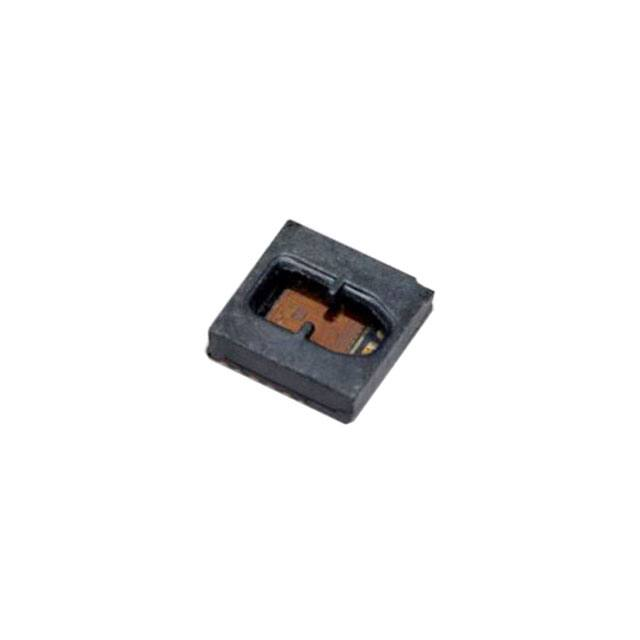
The encoder houses an infrared LED light source and
photo-detecting circuitry in a single package. The small size
of 4.00 mm (L) × 4.00 mm (W) × 1.05 mm (H), allows it to be
used in a wide range of miniature commercial applications
where size and space are primary concerns.
Analog Output option – Two channels differential
analog output and differential digital or analog index
output
Digital Output option – Three channels differential or
TTL compatible; two channel quadrature (AB) digital
outputs for direction sensing and a third channel, index
digital output
Built-in interpolator for 1x, 2x, 4x, 8x, and 16x
interpolation
Surface mount leadless package – 4.0 mm (L) ×
4.0 mm (W) × 1.05 mm (H)
Operating voltage of 3.3V and 5.0V supply
Built-in LED current regulation
Wide operating temperature range from –40°C to
125°C.
High encoding resolution: 225 LPI (lines/inch) or
8.86 LPmm (lines/mm)
Qualified automotive standard AEC-Q100 Grade 1
Applications
Closed-loop stepper motors
Small motors, actuators
Industrial printers
Robotics
Light detection and ranging (LiDAR)
Pan-tilt-zoom camera
Automated guided vehicles (AGVs)
Optometric equipment
Linear stages
Disclaimer: Except as expressly indicated in writing, the component is not designed or warranted to be suitable for use in
safely-related applications where its failure or malfunction can reasonably be expected to result in injury, death, or severe
equipment damage.
Broadcom
AEDR-9820A-DS105
September 22, 2021
�AEDR-9820A Data Sheet
3 Channels Reflective Incremental Encoders Analog and Digital Output (225 LPI)
Output Waveform
Analog Output Option
Code Wheel Rotation Movement (Anti-clockwise)
Analog Parameter Definitions
Analog Peak-to-Peak
Vpp
The peak-to-peak signal magnitude in V of the analog signal
Analog Offset
VOFFSET
The offset in mV from the mid-point of the analog peak-to-peak signal to
the zero voltage point
Analog Peak/Valley Voltage
VPA, VPB
The value in V of the peak/valley of the analog signal (that is, one-sided
reading)
VMA, VMB
Analog Peak to Peak Voltage
Broadcom
VPPA, VPPB
The absolute difference between VP and VM of channel A or B
AEDR-9820A-DS105
2
�AEDR-9820A Data Sheet
3 Channels Reflective Incremental Encoders Analog and Digital Output (225 LPI)
Digital Output Option
C
360
P
eDeg
A
Amp l i t u d e
S3
S2
S1
S4
B
P0
Index of 90 eDeg KƉƟon
I
P0
Index of 180 eDeg OpƟon
I
P0
I
Index of 360 eDeg OpƟon
Codewheel roƚĂƟon
movement (CCW)
Quadrature Signals A, B, and I
Digital Parameter Definitions
Count
N
The number of bar and window pairs or counts per revolution (CPR) of the code wheel.
Cycle
C
360 electrical degrees (°e), 1 bar and window pair.
One shaft rotation: 360 mechanical degrees, N cycles.
Cycle Error
C
An indication of cycle uniformity. The difference between an observed shaft angle that gives
rise to one electrical cycle, and the nominal angular increment of 1/N of a revolution.
Pulse Width (Duty) Error
P
The deviation, in electrical degrees, of the pulse width from its ideal value of 180°e.
State
S
The number of electrical degrees between a transition in the output of channel A and the
neighboring transition in the output of channel B. There are four states per cycle, each
nominally 90°e.
Phase
The number of electrical degrees between the center of the high state of channel A and the
center of the high state of channel B. This value is nominally 90°e for quadrature output.
Optical Radius
Index Pulse Width
Broadcom
ROP
P0
The distance from the code wheel's center of rotation to the optical center (O.C.) of the
encoder module.
The number of electrical degrees that an index is high in one cycle.
AEDR-9820A-DS105
3
�AEDR-9820A Data Sheet
3 Channels Reflective Incremental Encoders Analog and Digital Output (225 LPI)
Absolute Maximum Ratings
Storage Temperature, TS
–40°C to 150°C
Operating Temperature, TA
–40°C to 125°C
Supply Voltage, VCC
7V
ESD Human Body Model
4000V
ESD Charge Device Model
1000V
NOTE:
1. Proper operation of the encoder cannot be guaranteed if the maximum ratings are exceeded.
2. Caution: Take antistatic discharge precautions when handling the encoder to avoid damage, degradation, or
both induced by ESD.
3. Remove Kapton tape only after SMT reflow process and just before final assembly. Take precautions to keep
the encoder ASIC clean at all times.
4. Some particles may be present on the surface of the encoder ASIC surface. The presence of these particles
do not degrade the performance of the encoder.
Recommended Operating Condition
Parameter
Symbol
Min.
Typ.
Max.
Units
TA
–40
25
125
°C
Supply Voltage
VCC
2.97
3.3
3.63
V
4.5
5
5.5
Current
Icc
—
30
65
Pin Current (All I/O Outputs)
I
–20
—
20
mA
Maximum Output Frequency
F
—
—
200
kHz
At 1x interpolation
—
—
400
kHz
At 2x interpolation
—
—
800
kHz
At 4x interpolation
—
—
1.6
MHz
At 8x interpolation
—
—
2
MHz
At 16x interpolation
Operating Temperature
mA
Radial Misalignment
ER
—
—
± 0.2
mm
Tangential Misalignment
ET
—
—
± 0.2
mm
Tilt Misalignment
E
—
—
± 2.0
deg
Code Wheel Gap
G
0.5
1.00
1.5
mm
Notes
Ripple < 100 mVp-p
No load
Power-Up Behavior
When the AEDR-9820A is powered on, the A, B, and I digital outputs are invalid until after the initial first state of either Ch A
or Ch B signal.
Broadcom
AEDR-9820A-DS105
4
�AEDR-9820A Data Sheet
3 Channels Reflective Incremental Encoders Analog and Digital Output (225 LPI)
Encoder Pinout
Pin
Name
Function
1
CH_A / A+
Digital A+ / Analog Sin+
2
N.C.a
—
3
LED ANODE
LED Anode
4
LED ANODE
LED Anode
5
LED CATHODE
LED Cathode
18
N.C.
—
6
LED REG
LED Regulation
19
INDEX_SEL
—
7
VDDA / VCC
Analog Supply Voltage
20
CH_BB / B-
Digital B- / Analog Cos-
8
VSSA / AGND
Analog Ground
21
CH_B / B+
Digital B+ / Analog Cos+
9
SEL2
Mode Selection 2
22
VSSD / DGND
Digital Ground
10
SEL1
Mode Selection 1
23
VDD
Digital Supply Voltage
11
INDEX_N / I-
Index Output Z- (Digital/Analog)
24
CH_AB / A-
Digital A- / Analog Sin-
12
INDEX_P / I+
Index Output Z+ (Digital/Analog)
25
VSSA
Analog Ground
N.C.
—
(25)
N.C.
—
13
Pin
Name
Function
14
N.C.
—
15
N.C.
—
16
N.C.
—
17
N.C.
—
a. N.C. - No connect.
NOTE:
1. No connection to all corner pads indicated as (25).
2. Connect pin 8, pin 22, and pin 25 to common ground for all digital or analog mode applications. Pin 25 is the
center pad of the package.
3. Both pin 7 and pin 23 need to be powered during operation.
4. Both pin 5 and pin 6 need to be connected together.
Broadcom
AEDR-9820A-DS105
5
�AEDR-9820A Data Sheet
3 Channels Reflective Incremental Encoders Analog and Digital Output (225 LPI)
Select Options – Encoder Built-in Interpolation
SEL 1
SEL 2
IND SEL
Interpolation Factor
Index
Maximum Output
Frequency
CPR at ROP
4.6 mm
CPR at ROP
11 mm
Open
Open
Low
1X
Gated 90 deg
200 kHz
256
612
400 kHz
512
1224
800 kHz
1024
2448
1.6 MHz
2048
4896
2.0 MHz
4096
9792
200 kHz
N/A
N/A
Open
Low
High
Gated 180 deg
Open
Ungated raw
Low
2X
High
Open
High
High
Low
Low
Gated 360 deg
Low
4X
High
Gated 180 deg
Gated 360 deg
Low
8X
Gated 90 deg
Gated 180 deg
Open
Low
Gated 90 deg
Open
High
High
Gated 90 deg
Gated 180 deg
Gated 360 deg
Low
16X
Gated 90 deg
High
Gated 180 deg
Open
Gated 360 deg
Open
High
N/A
Analog (500 mVpp)
Analog
Low
High
N/A
Analog 1 Vpp
Ungated Digital
High / Low
Open
N/A
Analog 1 Vpp
Analog
NOTE:
Open selection must be connected to middle of a voltage divider circuit.
Vcc
4.7kɏ
SEL
4
4.7kɏ
NOTE:
Recommended to use 2 × 4.7-kΩ resistors (Vcc-GND).
The digital interpolation factor above may be used with the following equations to cater to various rotational speed (RPM)
and count per revolution (CPR).
RPM = (Count Frequency × 60) / CPR
The CPR (at 1X interpolation) is based on the following equation, which is dependent on radius of operation (ROP).
CPR = LPI × 2 × ROP (inch) or CPR = LP mm × 2 × ROP (mm)
NOTE:
Broadcom
LPmm (lines per mm) = LPI / 25.4.
AEDR-9820A-DS105
6
�AEDR-9820A Data Sheet
3 Channels Reflective Incremental Encoders Analog and Digital Output (225 LPI)
Recommended Setup for the Power Supply Pins and General Routing
VDDA, VDD, and the respective grounds (VSSA and VSSD) are to be connected as shown in the following figure. The
following are the recommended schematic design rules to follow:
Use a pair of 22-µF and 0.1-µF capacitors as bypass on VDD and VDDA. Place them in parallel as close as possible to
the encoder ASIC package, in between the power and ground pins.
Avoid routing the INDEX trace in parallel and close to the analog signals to reduce the INDEX signal switching noise
from coupling into the analog signal.
Design separate VDD and VDDA traces.
Minimize trace or cable length where possible.
For a single-ended application, do not ground the Output- from the encoder. Allow the output to float.
μ
μ
μ
μ
AEDR-9820A
NOTE:
1. Pin 25 is the center pad of the package and is designated as AGND.
2. Refer to the preceding table for SEL1X, SEL2X, and IND SEL configurations.
Broadcom
AEDR-9820A-DS105
7
�AEDR-9820A Data Sheet
3 Channels Reflective Incremental Encoders Analog and Digital Output (225 LPI)
Analog Encoder Characteristics
Parameter
Peak to Peak Voltage (Average)
Analog Offset Voltage
Symbol
Min.
Typical
Max.
Units
VPPA, VPPB
0.9
1
1.1
V
V
0.45
0.50
0.55
VOFFSETA, VOFFSETB
0.45 Vcc
0.5 Vcc
0.55 Vcc
V
Vref
—
Vcc / 2
—
V
Voltage Reference (Midpoint of signal Vpp)
NOTE:
1. Typical values represent the average value of encoder performance in our factory-based setup conditions.
2. The optimal performance of the encoder depending on the motor/system setup condition of the individual
customer.
Digital Signals Characteristics (Code Wheel of Rop at 4.6 mm)
Dynamic Performance
Parameter
Symbol
Typical
Interpolation Factor
Units
1X
2X
4X
8X
16X
±7
± 12
± 21
± 28
± 35
°e
Cycle Error
C
Pulse Width (Duty) Error
P
±6
± 13
± 14
± 18
± 25
°e
Phase Error
±3
±7
±7
±9
±9
°e
State Error
S
±6
±8
± 11
± 12
± 14
°e
Index Pulse Width (Gated 90°)
Po
90
90
90
90
90
°e
Index Pulse Width (Gated 180°)
Po
180
180
180
180
180
°e
Index Pulse Width (Gated 360°)
Po
N/A
360
360
360
360
°e
Index Pulse Width (Raw Ungated)
Po
330
N/A
N/A
N/A
N/A
°e
NOTE:
1. Typical values represent the average value of encoder performance based on factory setup conditions at
12k RPM with the metal code wheel.
2. The optimal performance of the encoder depending on the motor/system setup and code wheel type and condition.
Electrical Characteristics
Characteristics over recommended operating conditions at 25°C.
Parameter
Symbol
Min.
Typ.
Max.
Units
High Level Output Voltage
VOH
2.4
—
—
V
IOH = –20 mA
Low Level Output Voltage
IOH = +20 mA
VOL
—
—
0.4
V
Output current per channel, lout
lo
—
—
20
mA
Rise Timea
tr
—
< 50
—
ns
Fall Timea
tf
—
< 50
—
ns
Notes
CL ≤ 50 pF
a. Applicable for all digital modes except Index in Analog mode
Broadcom
AEDR-9820A-DS105
8
�AEDR-9820A Data Sheet
3 Channels Reflective Incremental Encoders Analog and Digital Output (225 LPI)
Code Wheel Design Guideline
The window tracks are reflective surfaces, and the bar tracks are opaque surfaces; all window and bar tracks are trapezoid.
The number of Incremental window/bar tracks depend on the CPR; and the Incremental windows/bars have the same width
value.
There is an offset between the Incremental window tracks and the Index window track.
There is only one Index window track, and its width is constant.
The center point to form the Incremental Optical Radius (Rop) and the Index Rop are two different points, except for 256 CPR.
Figure 1: Code Wheel Design (A)
Point B
a
Point A
Broadcom
AEDR-9820A-DS105
9
�AEDR-9820A Data Sheet
3 Channels Reflective Incremental Encoders Analog and Digital Output (225 LPI)
Figure 2: Code Wheel Design (B)
d = WIncremental_window
Incremental Track
Index Track
e = OffsetIncremental_window_left_edge-Center_Line
d = WIncremental_bar
Ro_Incremental
c
Rop_Incremental
b
Ri_Incremental
Ro_Index
b
Rop_Index
c
f = WIndex_window
Ri_Index
g = OffsetIndex_window_left_edge-Center_Line
NOTE: Code wheel facing
up. Encoder placed on top
of Code Wheel in this view.
Broadcom
Dimension
Formula
Constant for AEDR-9820A
Rop_Incremental (mm)
(25.4 / 225) × (CPR / 2)
—
Rop_Index (mm)
—
R4.0485 from Point B
Ro_Incremental
Rop_Incremental + c
—
Ri_Incremental
Rop_Incremental – b
—
Ro_Index
Rop_Index + b
—
Ri_Index
Rop_Index – c
—
a (mm)
Rop_Incremental – 4.5995
—
b (mm)
(0.551 – h) / 2
—
c (mm)
Ro_Incremental – Rop_Incremental or Rop_Index – Ri_Index
≥ 0.35
d (°)
(Pitch / 2) or ((360 / CPR) / 2)
—
e (°)
1.25d
—
f (°)
—
0.7031
g(°)
f/2
0.3516
h (mm)
Ro_Index – Ri_Incremental at Y-axis
0 ≥ h ≥ 0.05
AEDR-9820A-DS105
10
�AEDR-9820A Data Sheet
3 Channels Reflective Incremental Encoders Analog and Digital Output (225 LPI)
Code Wheel Design Example
The following demonstrates a code wheel design for the AEDR-9820A at 256 CPR.
Determine Rop_Incremental
(25.4 / 225) × (256 / 2)
Determine Ro_Incremental
4.5995 + 0.35
Determine Ri_Incremental
4.5995 – (0.551 / 2)
4.5995 mm
4.9495 mm
4.3240 mm
Determine Pitch
360 / 256
= 1.4062°
Determine d
1.406 / 2
= 0.7031°
Determine e
1.25 × 0.703
= 0.8789°
With the preceding information, draw a trapezoid based on Point A (0, 0), populate 256x at pitch = 1.4062°
Determine a
4.5995 – 4.5995
Rop_Index
= 0 mm
= 4.0485 mm
Ro_Index
4.0485 + (0.551 / 2)
= 4.3240 mm
Ri_Index
4.0485 – 0.35
= 3.6985 mm
f
g
= 0.7031°
f/2
= 0.3516°
With the preceding information, draw a trapezoid based on Point B (0, 0)
The following demonstrates a code wheel design for the AEDR-9820A at 1024 CPR.
Determine Rop_Incremental
(25.4 / 225) × (1024 / 2)
Determine Ro_Incremental
18.3980 + 0.35
Determine Ri_Incremental
18.3980 – (0.551 / 2)
18.3980 mm
18.7480 mm
18.1225 mm
Determine Pitch
360 / 1024
= 0.3516°
Determine d
0.3516 / 2
= 0.1758°
Determine e
1.25 × 0.1758
= 0.2197°
With the preceding information, draw a trapezoid based on Point A (0, 0), populate 1024x at pitch = 0.3516°
Determine a
18.3980 – 4.5995
Rop_Index
= 13.7985 mm
= 4.0485 mm
Ro_Index
4.0485 + (0.551 / 2)
= 4.3240 mm
Ri_Index
4.0485 – 0.35
= 3.6985 mm
f
g
= 0.7031°
f/2
= 0.3515°
With the preceding information, draw a trapezoid based on Point B (0, 13.7985)
Broadcom
AEDR-9820A-DS105
11
�AEDR-9820A Data Sheet
3 Channels Reflective Incremental Encoders Analog and Digital Output (225 LPI)
Code Strip Design Guideline
The Incremental/Index window track is a reflective surface and the Incremental bar track is opaque.
The window width is denoted by Wwindow and the bar width is denoted by Wbar.
All windows and bars has the same width value, d.
There is an offset between Incremental window track and Index window track, denoted by e.
NOTE: Code wheel facing
up. Encoder placed on top
of Code Wheel in this view.
Dimension
Pitch (mm)
Broadcom
Formula
225 LPI
25.4 / LPI
0.113
a (mm)
ROP_INC – ROP_INDEX
0.551
b (mm)
ROP_INC – RI_INC OR RO_INDEX – ROP_INDEX
a/2
c (mm)
RO_INC – ROP_INC OR ROP_INDEX – RI_INDEX
0.35
d (mm)
Pitch / 2
0.057
e (mm)
(3 / 4) × d
0.042
AEDR-9820A-DS105
12
�AEDR-9820A Data Sheet
3 Channels Reflective Incremental Encoders Analog and Digital Output (225 LPI)
Multiple Index Pulse Code Wheel or Strip Design Guideline
For pseudo absolute encoder applications, the multiple Index pulse can be designed into the code wheel or strip. The
minimum Index bar width is 3x the incremental pitch.
The recommended multiple Index pulse design guideline is shown in the following figure.
Package Outline Drawing
NOTE:
1. All dimensions are in mm.
2. Tolerance is x.xx ± 0.15 mm.
Broadcom
AEDR-9820A-DS105
13
�AEDR-9820A Data Sheet
3 Channels Reflective Incremental Encoders Analog and Digital Output (225 LPI)
Recommended Land Pattern
NOTE:
1. All dimensions are in mm.
2. Tolerance is x.xx ± 0.05 mm.
Broadcom
AEDR-9820A-DS105
14
�AEDR-9820A Data Sheet
3 Channels Reflective Incremental Encoders Analog and Digital Output (225 LPI)
Encoder Placement Orientation, Position, and Direction of Movement
The AEDR-9820A is designed with both the emitter and detector dice placed in parallel to the code wheel window/bar
orientation. The encoder package is mounted on top facing down onto the code wheel. When properly aligned, the detector
side will be closer to the center of the code wheel than the emitter.
The optical center of the encoder package must be aligned tangential to the code wheel’s Rop. The optimal gap setting
recommended is 1.00 mm, with the range of 0.50 mm to 1.50 mm.
Channel A leads Channel B when the code wheel rotates anticlockwise and vice versa.
Broadcom
AEDR-9820A-DS105
15
�AEDR-9820A Data Sheet
3 Channels Reflective Incremental Encoders Analog and Digital Output (225 LPI)
Moisture Sensitivity Level
The AEDR-9820A package is specified to moisture sensitive level 3 (MSL 3). Take precautions when handling this
moisture-sensitive product to ensure the reliability of the product.
Storage before use
An unopened moisture barrier bag (MBB) can be stored at < 40°C/90% RH for 12 months.
Open the MBB just prior to assembly.
Control after opening the MBB
Mount the encoder that will be subjected to reflow soldering within 168 hours of factory condition < 30°C/60% RH.
Control for unfinished reel
Store a sealed MBB with desiccant or desiccators at a < 5% RH condition.
Baking is required if the following conditions exist
The humidity indicator card (HIC) is > 10% when read at 23°C ± 5°C.
The encoder floor life exceeded 168 hours.
The recommended baking condition is 40°C ± 5°C for 22 hours (tape and reel) or 125°C ± 10°C for 1 hour (loose units).
Broadcom
AEDR-9820A-DS105
16
�AEDR-9820A Data Sheet
3 Channels Reflective Incremental Encoders Analog and Digital Output (225 LPI)
Recommended Lead Free Solder Reflow Soldering Temperature Profile
CAUTION! Exercise care when handling the encoder ASIC because it is a sensitive optical device. Remove the protective
Kapton tape only after the reflow process and just before final assembly.
Tape and Reel Information
Broadcom
AEDR-9820A-DS105
17
�AEDR-9820A Data Sheet
3 Channels Reflective Incremental Encoders Analog and Digital Output (225 LPI)
Reel Dimensions
Ordering Information
Accessories Ordering Information
Part Number
Description
HEDS-9820EVB
AEDR-9820 Evaluation Board 225 LPI Evaluation Board and Code Wheel
Broadcom
AEDR-9820A-DS105
18
�Copyright © 2020–2021 Broadcom. All Rights Reserved. The term “Broadcom” refers to Broadcom Inc. and/or its
subsidiaries. For more information, go to www.broadcom.com. All trademarks, trade names, service marks, and logos
referenced herein belong to their respective companies.
Broadcom reserves the right to make changes without further notice to any products or data herein to improve reliability,
function, or design. Information furnished by Broadcom is believed to be accurate and reliable. However, Broadcom does
not assume any liability arising out of the application or use of this information, nor the application or use of any product or
circuit described herein, neither does it convey any license under its patent rights nor the rights of others.
�