AEIC-7273-S16
Quad Differential Line Driver LC
With Open-Collector Outputs And Enable Function
Data Sheet
Description
Features
These line drivers are similar in function to the AEIC7272-S16, only in an open-collector format. The VCC
pin powers the internal logic only. Output voltage is
dependent on the customer supplied voltage, up to a
maximum of 30 V. There is essentially no difference in
output swing or performance with VCC (LOGIC) values
from 3.5-30 V. Internal clamp diodes allow trouble-free
operation when driving cable lengths exceeding 100
meters. The outputs are protected by initiating shutdown
when junction temperatures exceed safe limits. This
feature assures highly reliable operation in harsh environments. Heat sinking is aided by having pin 8 directly
connected to the ASIC substrate inside the package.
Supply (Bias) Voltage Range 3.5 V to 30 V
Operation to 800KHz
CMOS and TTL Compatible Inputs
Support RS422A
High Impedance Buffered Inputs with hysteresis
NPN Open-Collector outputs
80 mA peak SINK/SOURCE current
Outputs Protected by Thermal Shut-Down
Pin Assignment
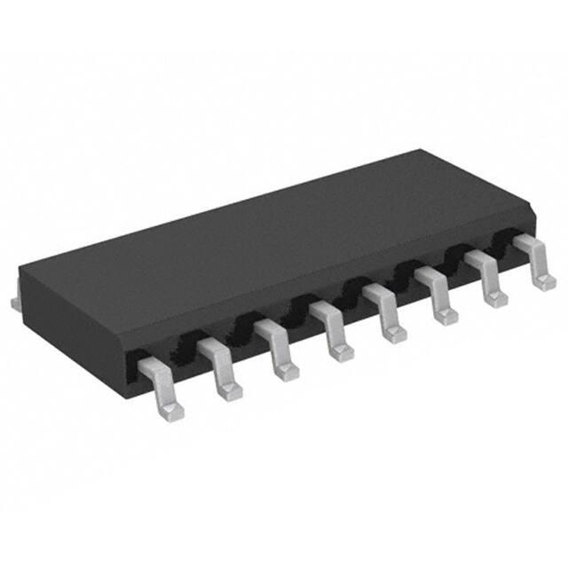
This part is available in 16L SOIC Pb-free) package.
AIN 1
16 NC
Applications
A+ 2
15 DIN
A- 3
14 D+
Encoders
Industrial controls
VCC
4
VREG
13 D-
B- 5
12 EN-
B+ 6
11 C-
BIN 7
10 C+
GND 8
9 CIN
�Table 1. Absolute Maximum Ratings
Parameters
Symbol
Min.
Max.
Units
Operating Temperature Range
TA
-55
125
°C
Supply (Driver) Voltage Range
VCCD
3.5
30
V
Notes
Table 2. Electrical Characteristics
Unless otherwise specified, TA = 25° C and EN- < 0.8 V.
Parameters
Symbol
Min.
Typ.
Max.
Units
Test Conditions
Overtemp Operate Point (junction)
TJOP
–
172
–
°C
Note 1
Overtemp Release Point (junction)
TJRP
–
136
–
°C
Note 1
Vcc Voltage Range
VCC
3.5
5
30
V
Supply Current VCC1
ICC1
–
11.9
16.0
mA
VCC = 5 V
Supply Current VCC2
ICC2
–
2.5
3.4
mA
VCC = 5 V, EN- > 2 V
Supply Current VCC3
ICC3
–
12.1
18.5
mA
VCC = 30 V
Supply Current VCC4
ICC2
–
2.6
3.5
mA
VCC = 30 V, EN- > 2 V
Enable Input Threshold
V THE
0.8
1.5
2
V
Enable Low Level Input Current
IILE
-10
0
10
A
VIN = 0 V, VCC = 5 V
Enable High Level Input Current
IIHE
–
108
150
A
VIN = 5 V, VCC = 5 V
High Impedance Output Leakage
IOZ
-4.0
0.0
4.0
A
VCC = 5 V, EN- > 2 V,
Output at 15 V
Input Positive-Going Threshold
V T+
1.05
1.25
1.45
V
Input Negative-Going Threshold
V T-
0.75
0.95
1.15
V
Input Hysteresis
VH
–
0.3
–
V
Low Level Input Current
IIL
-4.0
-0.1
–
A
VIN = 0 V, VCC = 5 V
High Level Input Current
IIH
–
0
4.0
A
VIN = 5 V, VCC = 5 V
Low Level Output1
VOL1
–
375
500
mV
IOL = 20 mA, VCC = 5 V,
VOC = 30 V
Low Level Output2
VOL2
–
370
500
mV
IOL = 20 mA, VCC = 30 V,
VOC = 30 V
High Level Output Current1
IOH1
–
0
10
A
VCC = 5 V, VOC = 30 V
High Level Output Current2
IOH2
–
0
10
A
VCC = 30 V, VOC = 30 V
Notes :
1. This is not a test parameter, but for information only.
2. Unused inputs should be connected to ground.
3. Do not leave pin 12 open. In applications which do not use the enable function, this pin should be tied to ground.
Table 3. AC Switching Characteristics
Load is 470 ohms and 1000 pF, output to its compliment and 470 ohms each output to Voc.
Parameters
Symbol
Min.
Typ.
Max.
Units
Test Conditions
Propagation delay, rising input 50% point
to zero crossing of differential outputs
TPLH
–
232
325
ns
See above.
Propagation delay, falling input 50% point
to zero crossing of differential outputs
TPHL
–
236
330
ns
See above.
Output Rise Time
TR
–
516
722
ns
See above.
Output Fall Time
TF
–
516
722
ns
See above.
2
�Package Drawings (Dimensions in Inches)
D
CL
X
CL
E
PIN NO. 1
ID MARK
0.010
2
e
DETAIL “A”
B
±0.004
0.015 X 45°
A
A1
16 SOIC
Symbol
Min
Max
A
0.054
0.068
A1
0.004
0.0098
B
0.014
0.019
D
0.386
0.393
E
0.150
0.157
H
0.229
0.244
e
0.0075
0.0098
L
0.016
0.034
X
θ1
θ2
H
Notes:
1. Lead coplanarity should be o to 0.004" max.
2. Package surface finishing: VD1 24~27 (Dual).
Package surface finishing: VD1 13~15 (16L Soic(NB) Matrix).
3. All dimension excluding mold flashes.
4. The lead width, B to be determined at 0.0075" from the lead tip.
0.020 REF
0°
8°
7° BSC
For product information and a complete list of distributors, please go to our web site:
DETAIL “A”
C
1
0.050 BSC
C
L
GAUGE PLANE
SEATING PLANE
www.avagotech.com
Avago, Avago Technologies, and the A logo are trademarks of Avago Technologies in the United States and other countries.
Data subject to change. Copyright © 2005-2011 Avago Technologies. All rights reserved.
AV02-3022EN - July 8, 2011
�
很抱歉,暂时无法提供与“AEIC-7273-S16”相匹配的价格&库存,您可以联系我们找货
免费人工找货