Data Sheet
ALMD-LY3G-12x02
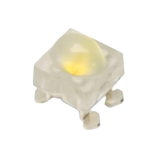
High Brightness SMT Oval White LED Lamps
Overview
The new Broadcom® ALMD-LY3G series is essentially like
a conventional high-brightness through-hole LED in the
form of a surface-mount device. It can be assembled using
common SMT assembly processes and is compatible with
industrial soldering processes.
The LEDs are made with an advanced optical grade epoxy
for superior performance in outdoor sign applications. For
easy pick-and-place assembly, the LEDs are packed in tape
and reel format. Every reel is shipped in a single intensity
and color bin to ensure uniformity.
Features
High brightness InGaN
Diffused lens
Typical viewing angle: 90 × 45°
JEDEC MSL3
Compatible with industrial reflow soldering process
Applications
Gas price signs
Monocolor signs
CAUTION!
This LED is ESD sensitive. Please observe appropriate precautions during handling and processing. Refer to application
note AN-1142 for additional details.
The LED must be kept in a moisture barrier bag with < 5% relative humidity (RH) when not in use because prolonged
exposure to the environment might cause the leads to tarnish or rust, which might cause difficulties in soldering.
Broadcom
ALMD-LY3G-12x02-DS100
September 27, 2017
�ALMD-LY3G-12x02 Data Sheet
High Brightness SMT Oval White LED Lamps
Figure 1: Package Drawing
NOTE:
1. All dimensions in millimeters (mm).
2. Tolerance is ±0.20 mm unless otherwise specified.
3. Mildsteel leadframe.
Device Selection Guide (TJ = 25°C, IF = 20 mA)
Chromaticity
Coordinate
Part Number
Typ.
Luminous Intensity, IV (mcd)a, b
Min.
Max.
Color Bin
ALMD-LY3G-12002
0.285, 0.262
2900
4200
1, 2, 3, 4, 5, 6
ALMD-LY3G-12R02
0.285, 0.262
2900
4200
1, 2, 3, 4
ALMD-LY3G-12G02
0.285, 0.262
2900
4200
2, 3, 4
a. The luminous intensity, IV is measured at the mechanical axis of the LED package and it is tested with mono pulse current. The actual peak
of the spatial radiation pattern may not align with the mechanical axis.
b. Tolerance is ±15%.
Broadcom
ALMD-LY3G-12x02-DS100
2
�ALMD-LY3G-12x02 Data Sheet
High Brightness SMT Oval White LED Lamps
Absolute Maximum Ratings
Parameters
White
Units
DC Forward Currenta
30
mA
Peak Forward Currentb
100
mA
Power Dissipation
Reverse Voltage
105
mW
Not recommended for reverse bias
V
LED Junction Temperature
100
°C
Operating Temperature Range
–40 to +85
°C
Storage Temperature Range
–40 to +100
°C
a. Derate linearly as shown in Figure 12.
b. Duty factor = 10%, frequency = 1 kHz.
Optical and Electrical Characteristics (TJ = 25°C, IF = 20 mA)
Parameters
Min.
Typ.
Max.
Units
Viewing Angle, 2½a
—
90 × 45
—
°
Forward Voltage, VFb
2.70
2.90
3.50
V
Reverse Voltage, VR at IR = 10 µAc
5
—
—
V
Chromaticity Coordinate
—
0.285, 0.262
—
—
—
350
—
°C/W
Thermal Resistance,
RθJ-Pd
a. ½ is the off-axis angle where the luminous intensity is ½ the peak intensity. The actual peak of the spatial radiation pattern may not align with
the mechanical axis.
b. Tolerance is ±0.05V.
c. Indicates product final test condition only. Long term reverse bias is not recommended.
d. Thermal resistance from LED junction to pin.
Broadcom
ALMD-LY3G-12x02-DS100
3
�ALMD-LY3G-12x02 Data Sheet
High Brightness SMT Oval White LED Lamps
Part Numbering System
A
L
M
D
-
x1
Y
3
x2
-
x3
x4
x5
x6
Code
Description
Option
x1
Package type
L
x2
Lens appearance
G
Diffused
x3
Minimum intensity bin
1
2900–3500
x4
Maximum intensity bin
2
3500–4200
x5
Color bin
0
Bin 1, 2, 3, 4, 5, 6
R
Bin 1, 2, 3, 4
G
Bin 2, 3, 4
02
Tested at 20 mA
x6x7
Packaging 0ption
x7
SMT oval
Part Number Example
ALMD-LY3G-12002
x1 : L
–
SMT oval
x2 : G
–
Diffused
x3 : 1
–
Minimum intensity bin 1
x4 : 2
–
Maximum intensity bin 2
x5 : 0
–
Color bin 1, 2, 3, 4, 5, 6
x6 x7: 02
–
Tested at 20 mA
Broadcom
ALMD-LY3G-12x02-DS100
4
�ALMD-LY3G-12x02 Data Sheet
High Brightness SMT Oval White LED Lamps
Bin Information
Figure 2: Chromaticity Diagram
0.34
Luminous Intensity Bin Limits (CAT)
0.32
Luminous Intensity (mcd)
Min.
1
2900
3500
2
3500
4200
Tolerance = ±15%
Example of bin information on reel and packaging label:
CAT : 1
–
Intensity bin 1
BIN : 3
–
Color bin 3
x
y
1
0.260
0.243
0.270
0.260
0.288
0.240
0.279
0.225
0.270
0.260
0.280
0.275
0.294
0.250
0.288
0.240
0.280
0.275
0.290
0.290
0.300
0.260
0.294
0.250
0.290
0.290
0.300
0.305
0.307
0.270
0.300
0.260
0.300
0.305
0.310
0.320
0.315
0.280
0.307
0.270
0.310
0.320
0.320
0.333
0.323
0.293
0.310
0.320
5
6
4
0.28
3
2
0.26
0.22
Bin ID
4
5
0.24
Chromaticity Coordinates
3
0.30
1
Color Bin Limits (BIN)
2
6
Max.
y coordinate
Bin ID
0.22
0.24
0.26
0.28
0.3
x coordinate
0.32
0.34
Tolerance = ±0.01
Broadcom
ALMD-LY3G-12x02-DS100
5
�ALMD-LY3G-12x02 Data Sheet
High Brightness SMT Oval White LED Lamps
Figure 3: Spectral Power Distribution
Figure 4: Forward Current vs. Forward Voltage
30
1.0
0.9
25
FORWARD CURRENT - mA
RELATIVE INTENSITY
0.8
0.7
0.6
0.5
0.4
0.3
0.2
15
10
5
0.1
0.0
0
380
430
480
530
580
630
WAVELENGTH - nm
680
730
0.0
780
Figure 5: Relative Luminous Intensity vs. Mono Pulse Current
2.0
3.0
FORWARD VOLTAGE - V
4.0
5.0
Figure 6: Chromaticity Coordinate Shift vs. Mono Pulse Current
1.6
0.004
1.4
0.003
0.002
1.2
0.001
1.0
0.000
0.8
-0.001
Cx
-0.002
0.6
Cy
-0.003
0.4
-0.004
0.2
-0.005
0.0
-0.006
0
10
20
30
MONO PULSE CURRENT- mA
40
Figure 7: Relative Light Output vs. Junction Temperature
0
5
10
15
20
25
MONO PULSE CURRENT - mA
30
35
Figure 8: Forward Voltage Shift vs. Junction Temperature
0.20
100
0.15
RELATIVE LIGHT OUTPUT - %
(NORMALIZED AT 25°C)
FORWARD VOLTAGE SHIFT - V
(NORMALIZED AT 25°C)
120
0.10
80
0.05
60
0.00
40
-0.05
20
-0.10
0
-50
Broadcom
1.0
CHROMATICITY COORDINATE SHIFT
(NORMALIZED AT 20 mA)
RELATIVE LUMINOUS INTENSITY - mcd
(NORMALIZED AT 20mA)
20
-25
0
25
50
75
JUNCTION TEMPERATURE, TJ - °C
100
125
-50
-25
0
25
50
75
JUNCTION TEMPERATURE, TJ - °C
100
125
ALMD-LY3G-12x02-DS100
6
�ALMD-LY3G-12x02 Data Sheet
High Brightness SMT Oval White LED Lamps
Figure 9: Chromaticity Coordinate Shift vs. Junction Temperature
Figure 10: Radiation Pattern for X-axis
0.015
0.9
0.010
0.8
0.005
0.000
RELATIVE INTENSITY
1.0
CHROMATICITY COORDINATE SHIFT
(NORMALIZED AT 25°C)
0.020
Cy
Cx
-0.005
-0.010
0.6
0.5
0.4
0.3
-0.015
0.2
-0.020
0.1
0.0
-0.025
-50
-25
0
25
50
75
JUNCTION TEMPERATURE, TJ - °C
100
-90
125
Figure 11: Radiation Pattern for Y-axis
-60
-30
0
30
ANGULAR DISPLACEMENT - DEGREE
60
90
Figure 12: Maximum Forward Current vs. Ambient
Temperature. Derated based on TJMAX = 100°C
35
1.0
MAX. ALLOWABLE DC CURRENT - mA
0.9
0.8
RELATIVE INTENSITY
0.7
0.7
0.6
0.5
0.4
0.3
0.2
0.1
0.0
30
25
20
RTJ-A = 713°C/W
15
10
5
0
-90
-60
-30
0
30
ANGULAR DISPLACEMENT - DEGREE
60
90
0
20
40
60
AMBIENT TEMPERATURE, TA - °C
80
100
Figure 13: Recommended Soldering Land Pattern
NOTE: Recommended stencil
thickness is 6 mils minimum
NOTE:
Broadcom
All dimensions are in millimeters (mm).
ALMD-LY3G-12x02-DS100
7
�ALMD-LY3G-12x02 Data Sheet
High Brightness SMT Oval White LED Lamps
Figure 14: Carrier Tape Dimensions
NOTE:
1. All dimensions are in millimeters (mm).
2. Tolerance is ± 0.20 mm unless otherwise specified.
Figure 15: Reel Dimensions
+2.0
16.400 - 0
330 MAX.
100 ±0.50
+0.5
13.000 - 0.2
ANODE LEADS
UNREELING DIRECTION
NOTE:
Broadcom
All dimensions are in millimeters (mm).
ALMD-LY3G-12x02-DS100
8
�ALMD-LY3G-12x02 Data Sheet
High Brightness SMT Oval White LED Lamps
Precautionary Notes
Handling Precautions
Soldering
Do not perform reflow soldering more than twice.
Observe necessary precautions of handling moisturesensitive devices as stated in the following section.
Do not apply any pressure or force on the LED during
reflow and after reflow when the LED is still hot.
Use reflow soldering to solder the LED. Use hand
soldering only for rework if unavoidable, but it must be
strictly controlled to following conditions:
– Soldering iron tip temperature = 315°C maximum
– Soldering duration = 3s maximum
– Number of cycles = 1 only
– Power of soldering iron = 50W maximum
Do not touch the LED package body with the soldering
iron except for the soldering terminals, because it may
cause damage to the LED.
Confirm beforehand whether the functionality and
performance of the LED is affected by soldering with
hand soldering.
For automated pick-and-place, Broadcom has tested the
following nozzle size to work well with this LED. However,
due to the possibility of variations in other parameters, such
as pick-and-place machine maker/model, and other settings
of the machine, verify that the selected nozzle will not cause
damage to the LED.
Figure 18: Recommended Nozzle Dimension
NOTE:
Figure 16: Recommended Lead-Free Reflow Soldering Profile
1. The nozzle tip must touch the LED flange
during pick and place.
2. The outer dimensions of the nozzle tip must be
able to fit into the carrier tape pocket until it
touches the LED flange.
TEMPERATURE
10 to 30 SEC.
217°C
200°C
255 – 260°C
3°C/SEC. MAX.
3. All dimensions are in millimeters (mm).
6°C/SEC. MAX.
150°C
3°C/SEC. MAX.
60 – 120 SEC.
100 SEC. MAX.
TIME
Figure 17: Recommended Board Reflow Direction
Broadcom
Handling of Moisture-Sensitive Devices
This product has a Moisture Sensitive Level 3 rating per
JEDEC J-STD-020. Refer to Broadcom Application Note
AN5305, Handling of Moisture Sensitive Surface Mount
Devices for additional details and a review of proper
handling procedures.
Before use:
– An unopened moisture barrier bag (MBB) can be
stored at < 40°C/90% RH for 12 months. If the actual
shelf life has exceeded 12 months and the humidity
indicator card (HIC) indicates that baking is not
required, it is safe to reflow the LEDs per the original
MSL rating.
– Do not open the MBB prior to assembly (for
example, for IQC). If unavoidable, the MBB must be
properly resealed with fresh desiccant and HIC. The
exposed duration must be taken in as floor life.
ALMD-LY3G-12x02-DS100
9
�ALMD-LY3G-12x02 Data Sheet
Control after opening the MBB:
– Read the HIC immediately upon opening of MBB.
– Keep the LEDs at < 30°C/60% RH at all times, and
complete all high temperature-related processes,
including soldering, curing, or rework within 168 hours.
Control for the unfinished reel:
High Brightness SMT Oval White LED Lamps
Application Precautions
Store unused LEDs in a sealed MBB with desiccant or a
desiccator at < 5% RH.
Control of the assembled boards:
If the PCB soldered with the LEDs is to be subjected to
other high-temperature processes, store the PCB in a
sealed MBB with desiccant or desiccator at < 5% RH to
ensure that all LEDs have not exceeded their floor life of
168 hours.
Baking is required if:
– The HIC indicator indicates a change in color for
10% and 5%, as stated on the HIC.
– The LEDs are exposed to conditions of > 30°C/60%
RH at any time.
– The LED's floor life exceeded 168 hours.
The recommended baking condition is: 60°C ± 5ºC for
20 hours.
Baking can only be done once.
Storage:
The soldering terminals of these Broadcom LEDs are
silver plated. If the LEDs are exposed in ambient
environments for too long, the silver plating might be
oxidized, thus affecting its solderability performance. As
such, keep unused LEDs in a sealed MBB with
desiccant or in a desiccator at < 5% RH.
The drive current of the LED must not exceed the
maximum allowable limit across temperature as stated
in the data sheet. Constant current driving is
recommended to ensure consistent performance.
Circuit design must cater to the whole range of forward
voltage (VF) of the LEDs to ensure the intended drive
current can always be achieved.
The LED exhibits slightly different characteristics at
different drive currents, which may result in a larger
variation of performance (meaning: intensity,
wavelength, and forward voltage). Set the application
current as close as possible to the test current to
minimize these variations.
The LED is not intended for reverse bias. Use other
appropriate components for such purposes. When
driving the LED in matrix form, ensure that the reverse
bias voltage does not exceed the allowable limit of the
LED.
White LEDs must not be exposed to acidic
environments and must not be used in the vicinity of
any compound that may have acidic outgas, such as,
but not limited to, acrylate adhesive. These
environments have an adverse effect on LED
performance.
As actual application might not be exactly similar to the
test conditions, do verify that the LED will not be
damaged by prolonged exposure in the intended
environment.
Avoid rapid changes in ambient temperature, especially
in high-humidity environments, because they cause
condensation on the LED.
If the LED is intended to be used in harsh or outdoor
environments, protect the LED against damages
caused by rain water, water, dust, oil, corrosive gases,
external mechanical stresses, and so on.
Eye Safety Precautions
LEDs may pose optical hazards when in operation. Do not
look directly at operating LEDs because it might be harmful
to the eyes. For safety reasons, use appropriate shielding or
personal protective equipment.
Broadcom
ALMD-LY3G-12x02-DS100
10
�Disclaimer
Broadcom's products and software are not specifically designed, manufactured, or authorized for sale as parts, components,
or assemblies for the planning, construction, maintenance, or direct operation of a nuclear facility or for use in medical
devices or applications. The customer is solely responsible, and waives all rights to make claims against Broadcom or its
suppliers, for all loss, damage, expense, or liability in connection with such use.
Broadcom, the pulse logo, Connecting everything, Avago Technologies, Avago, and the A logo are among the trademarks
of Broadcom and/or its affiliates in the United States, certain other countries and/or the EU.
Copyright © 2017 by Broadcom. All Rights Reserved.
The term “Broadcom” refers to Broadcom Limited and/or its subsidiaries. For more information, please visit
www.broadcom.com.
Broadcom reserves the right to make changes without further notice to any products or data herein to improve reliability,
function, or design. Information furnished by Broadcom is believed to be accurate and reliable. However, Broadcom does
not assume any liability arising out of the application or use of this information, nor the application or use of any product or
circuit described herein, neither does it convey any license under its patent rights nor the rights of others.
�