物料型号:
- ASMC-PxB9-Txxxx
器件简介:
- Envisium是Avago和Lumileds提供的中功率LED的顶级类别,利用这两个行业领导者的最佳固态照明技术。Envisium LED提供无与伦比的性能、工程和设计灵活性。这是客户首次拥有中功率LED的选项。
引脚分配:
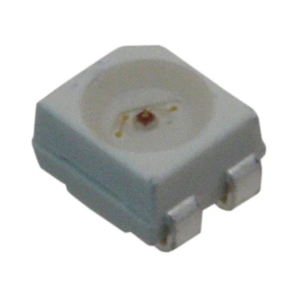
- PLCC-4(塑料引线芯片载体)
参数特性:
- 行业标准的PLCC-4封装
- 高可靠性LED封装
- 中功率亮度,使用TS AlInGaP芯片技术实现最佳通量性能
- 提供红色、红橙色和琥珀色
- 高光学效率
- 与PLCC-2相比,在相同电流下可以承受更高的环境温度
- 超宽视角120°
- 8mm载体胶带,7英寸卷轴
- 兼容IR和TTW焊接工艺
功能详解:
- Envisium Power PLCC-4 SMT LED是Avago PLCC-4 SMT LED的扩展。由于其优越的封装设计,该封装可以承受高电流驱动。与传统PLCC-2 SMT LED相比,该产品能更有效地散热,产生更高的光输出和更好的通量性能。
- 这些LED设计用于更高的可靠性、更好的性能,并能在广泛的环境条件下运行。这些新的中功率LED的性能特性使它们特别适合在恶劣条件下使用,例如在汽车应用以及电子标志和信号中。
- 为了便于轻松的拾放组装,LED被包装在符合EIA标准的胶带和卷轴中。每个卷轴都以单一强度和颜色箱发货(红色除外),以提供接近的均匀性。这些LED与IR焊接回流工艺兼容。由于这些产品的高可靠性特性,它们也可以通过波峰焊接工艺安装。
应用信息:
- 汽车内部 - 仪表盘背光 - 中控台背光 - 导航和音响系统 - 按钮背光
- 汽车外部 - 转向灯 - 侧重复器 - CHMSL - 后组合灯 - 积水灯
- 电子标志和信号 - 渠道字母 - 轮廓照明 - 室内可变信息标志
- 办公自动化、家用电器、工业设备 - 前面板背光 - 按钮背光 - 显示背光
封装信息:
- 提供了封装尺寸图,所有尺寸单位为毫米。