Data Sheet
ASMG-ST00-00001
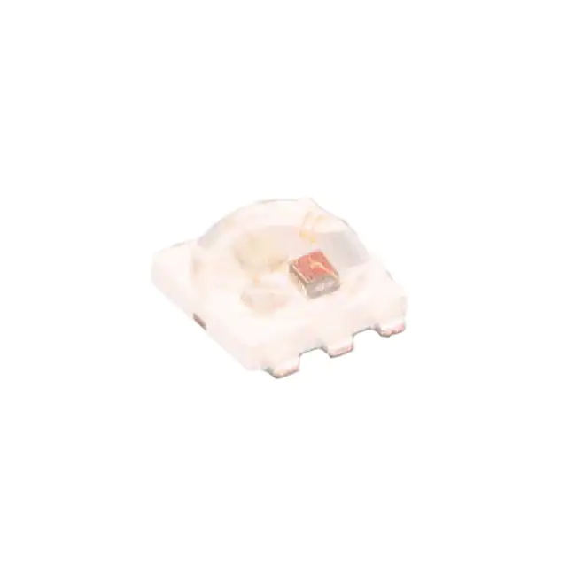
3W Tri-Color High Power LED
Description
The Broadcom® 3W Tri-Color High Power LED Light Source
is a high-performance, energy-efficient device that can
handle high thermal and high driving current.
The low-profile package design is suitable for a wide variety
of applications, especially where height is a constraint.
Features
The package is compatible with the reflow soldering
process. This will give more freedom and flexibility to the
light source designer.
Available in tri-color
Energy efficient
Compatible with reflow soldering process
High current operation
Long operation life
Wide viewing angle
Silicone encapsulation
MSL 1 products
Applications
Sign backlight
Retail display
Commercial lighting
Decorative lighting
Architectural lighting
CAUTION! This LED is Class 1B ESD sensitive per ANSI/ESDA/JEDEC JS-001. Please observe appropriate precautions
during handling and processing. Refer to Application Note AN-1142 for additional details.
Broadcom
ASMG-ST00-DS100
March 23, 2018
�ASMG-ST00-00001 Data Sheet
3W Tri-Color High Power LED
Package Dimensions
NOTE:
1. All dimensions are in millimeters (mm).
2. Tolerance is ± 0.2 mm unless otherwise specified.
3. Encapsulation = silicone.
4. Terminal finish = silver plating.
5. Thermal pad is connected to the anode of red.
Device Selection Guide
TJ = 25°C, IF = 350 mA.
Luminous Flux, ØV (lm) at 350 mAa, b
Part Number
ASMG-ST00-00001
Color
Min.
Typ.
Max.
Dice Technology
Red
45
55
65
AllnGaP
Green
80
95
112
InGaN
Blue
18
20
26
InGaN
a. ØV is the total luminous flux output as measured with an integrating sphere at 25ms mono pulse condition.
b. Luminous flux tolerance = ±10%.
Broadcom
ASMG-ST00-DS100
2
�ASMG-ST00-00001 Data Sheet
3W Tri-Color High Power LED
Absolute Maximum Ratings
Parameter
AllnGaP
InGaN
Unit
DC Forward Currenta
350
350
mA
Peak Forward Currentb
500
500
mA
980
1330
mW
Power Dissipation
Reverse Voltage
Not designed for reverse bias
LED Junction Temperature
120
°C
Operating Temperature Range
-40 to +100
°C
Storage Temperature Range
-40 to +120
°C
a. Derate linearly as shown in Figure 7 and Figure 8.
b. Duty factor = 10%, frequency = 1 kHz.
Optical Characteristics
IF = 350 mA, TJ = 25°C.
Dominant Wavelength, d (nm)a, b
Color
Min.
Typ.
Max.
Peak
Wavelength, p Viewing Angle,
2θ1/2 (°)c
(nm)
Typ.
Typ.
Red
613.5
623.0
631.0
631.5
135
Green
515.0
525.0
535.0
518.5
170
Blue
455.0
465.0
475.0
456.5
135
a. The dominant wavelength is derived from the CIE Chromaticity Diagram and represents the perceived color of
the device.
b. Tolerance = ± 1 nm.
c. 2θ½ is the off axis angle where the luminous intensity is half of the peak intensity.
Electrical Characteristics
TJ = 25°C.
Forward Voltage, VF (V)a at IF = 350 mA
Thermal Resistance, RθJ-S
(°C/W)b
Min.
Typ.
Max.
Reverse Current, IR (µA) at
VR = 5V
Red
1.8
2.2
2.8
Not designed for reverse bias
Green
2.8
3.4
3.8
10
Blue
2.8
3.4
3.8
6
Color
Typ.
6
a. Tolerance = ±0.1V.
b. Thermal resistance from LED junction to solder point.
Broadcom
ASMG-ST00-DS100
3
�ASMG-ST00-00001 Data Sheet
3W Tri-Color High Power LED
Part Numbering System
A
S
M
G
-
S
T
0
Code
Description
Option
x1 x2
Flux bin selection
00
x3
Color bin selection
0
0
-
Red:
0
x1
x2
x3
1
45–65 lm
Green:
80–112 lm
Blue:
18–26 lm
Red:
Bins 2 and 4
Green:
Bins A, 1, 2, and 3
Blue:
Bins A,1, 2, and 3
Bin Information
Luminous Flux Bin Limit
Example of bin information on reel and packaging label:
Luminous flux (lm) at 350 mA
Color
Min.
Max.
Red
45
65
Green
80
112
Blue
18
26
BIN:
2A3
→ Red color bin 2
→ Green color bin A
→ Blue color bin 3
Tolerance = ±10%.
Color Bin Limits (BIN)
Dominant Wavelength (nm) at
350 mA
Color
Bin ID
Min.
Max.
Red
2
613.5
620.5
4
620.5
631.0
Green
A
515.0
520.0
1
520.0
525.0
2
525.0
530.0
Blue
3
530.0
535.0
A
455.0
460.0
1
460.0
465.0
2
465.0
470.0
3
470.0
475.0
Tolerance = ±1 nm.
Broadcom
ASMG-ST00-DS100
4
�ASMG-ST00-00001 Data Sheet
3W Tri-Color High Power LED
Figure 1: Relative Luminous Flux vs. Mono Pulse Current
Figure 2: Forward Current vs. Forward Voltage
350
1
Red
Green
Blue
0.9
0.8
250
FORWARD CURRENT - mA
0.7
RELATIVE LUMINOUS FLUX
(NORMALIZED AT 350 mA)
Red
Green/Blue
300
0.6
0.5
0.4
0.3
0.2
200
150
100
50
0.1
0
0
0
50
100
150
200
250
300
0
350
0.5
1
1.5
2
2.5
FORWARD VOLTAGE - V
MONO PULSE CURRENT - mA
Figure 3: Dominant Wavelength Shift vs. Mono Pulse Current
Red
Green
Blue
8
140
120
RELATIVE LIGHT OUTPUT - %
(NORMALIZED AT 25 °C)
DOMINANT WAVELENGTH SHIFT - nm
(NORMALIZED AT 350 mA)
4
160
10
6
4
2
0
100
80
60
Red
40
Green
20
Blue
0
-2
0
50
100
150
200
250
300
25
350
50
75
MONO PULSE CURRENT - mA
100
125
JUNCTION TEMPERATURE, T J -°C
Figure 5: Forward Voltage Shift vs. Junction Temperature
Figure 6: Dominant Wavelength Shift vs. Junction
Temperature
8.0
0.2
Red
0.1
Blue
0.0
Red
6.0
Green
DOMINANT WAVELENGTH SHIFT - nm
(NORMALIZED AT 25°C)
FORWARD VOLTAGE SHIFT - V
(NORMALIZED AT 25°C)
3.5
Figure 4: Relative Light Output vs. Junction Temperature
12
-0.1
-0.2
-0.3
Green
Blue
4.0
2.0
0.0
-2.0
-0.4
25
50
75
JUNCTION TEMPERATURE, TJ - °C
Broadcom
3
100
125
25
50
75
100
125
JUNCTION TEMPERATURE, T J -°C
ASMG-ST00-DS100
5
�ASMG-ST00-00001 Data Sheet
3W Tri-Color High Power LED
Figure 8: Derating Curve According to Ambient Temperature
(TA) . Derated based on TJMAX = 120°C, RθJ-A = 30°C/W for Red
and Blue and RθJ-A = 34°C/W for Green.
400
400
350
350
300
300
250
MAX ALLOWABLE DC CURRENT - mA
MAX ALLOWABLE DC CURRENT - mA
Figure 7: Derating Curve According to Solder Point
Temperature (TS)
200
150
100
50
0
0
20
40
60
80
100
Red
Green
Blue
250
200
150
100
50
0
120
0
20
SOLDER POINT TEMPERATURE, T S - °C
Figure 9: Pulse Handling Capability at TS ≤ 100°C for AllnGaP
100
120
0.60
DF =
0.05
0.10
0.25
0.50
1.00
0.50
0.45
0.50
0.40
0.35
0.30
0.25
1E-05
0.0001
0.001
0.01
0.1
1
DF =
0.05
0.10
0.25
0.50
1.00
0.55
IP - PULSE CURRENT - A
0.55
I P - PULSE CURRENT - A
60
80
AMBIENT TEMPERATURE, T A - °C
Figure 10: Pulse Handling Capability at TS ≤ 100°C for InGaN
0.60
0.45
0.40
0.35
0.30
0.25
1E-05
10
0.0001
0.001
0.01
0.1
1
10
60
90
t p - PULSE DURATION - sec
t p - PULSE DURATION - sec
Figure 11: Radiation Pattern for Red
Figure 12: Radiation Pattern for Green
1.00
1.00
0.75
0.75
NORMALIZED INTENSITY
NORMALIZED INTENSITY
40
0.50
0.25
0.00
0.50
0.25
0.00
-90
Broadcom
-60
-30
0
30
ANGULAR DISPLACEMENT - DEGREES
60
90
-90
-60
-30
0
30
ANGULAR DISPLACEMENT - DEGREES
ASMG-ST00-DS100
6
�ASMG-ST00-00001 Data Sheet
3W Tri-Color High Power LED
Figure 13: Radiation Pattern for Blue
Figure 14: Spectral Power Distribution
1.00
1.0
0.9
0.8
0.7
RELATIVE INTENSITY
NORMALIZED INTENSITY
0.75
0.50
0.25
0.6
0.5
0.4
0.3
0.2
0.1
0.00
0.0
-90
-60
-30
0
30
60
90
ANGULAR DISPLACEMENT - DEGREES
380
430
480
530
580
630
WAVELENGTH - nm
680
730
780
Figure 15: Recommended Soldering Land Pattern (mm)
Units: mm.
Broadcom
ASMG-ST00-DS100
7
�ASMG-ST00-00001 Data Sheet
3W Tri-Color High Power LED
Figure 16: Carrier Tape Dimensions
CATHODE MARK
NOTE:
1. Drawing not to scale.
2. All dimensions are in millimeters.
3. Tolerance is ± 0.10 mm unless otherwise specified.
Broadcom
ASMG-ST00-DS100
8
�ASMG-ST00-00001 Data Sheet
3W Tri-Color High Power LED
Figure 17: Reel Dimensions
NOTE:
1. 500 pieces per reel.
2. Drawing not to scale
3. All dimensions are in millimeters.
Broadcom
ASMG-ST00-DS100
9
�ASMG-ST00-00001 Data Sheet
3W Tri-Color High Power LED
Soldering
Recommended reflow soldering conditions:
Figure 18: Recommended Reflow Soldering Profile
TEMPERATURE
10 - 30 SEC.
217 qC
200 qC
255 - 260 qC
3°C/SEC. MAX.
6°C/SEC. MAX.
150 qC
3 qC/SEC. MAX.
100 SEC. MAX.
60 - 120 SEC.
TIME
(Acc. to J-STD-020C)
Do not perform reflow soldering more than twice.
Do not apply any pressure or force on the LED during
reflow and after reflow when the LED is still hot.
Use reflow soldering to solder the LED. Hot plate
should only be used for rework if unavoidable but must
be strictly controlled to the following conditions:
– LED temperature = 260°C max.
– Time at maximum temperature = 20s max.
Confirm beforehand whether the functionality and
performance of the LED is affected by soldering with
hot plate.
Hand soldering is not recommended.
Precautionary Notes
Figure 19: Nozzle Size
Do not poke sharp objects into the silicone encapsulant.
Sharp objects, such as tweezers or syringes, might
apply excessive force or even pierce through the
silicone and induce failures to the LED die or wire bond.
Broadcom
Storage
The soldering terminals of these LEDs are silver plated.
If the LEDs are exposed in an ambient environment for
too long, the silver plating might be oxidized and thus
affecting its solderability performance. As such, keep
unused LEDs in a sealed moisture barrier bag (MBB)
with desiccant or in desiccator at
很抱歉,暂时无法提供与“ASMG-ST00-00001”相匹配的价格&库存,您可以联系我们找货
免费人工找货