AVAGO ASMT-CR00
AlInGaP Red
0.4mm Low Profile
Right Angle Surface Mount ChipLED
Datasheet
Features
Description
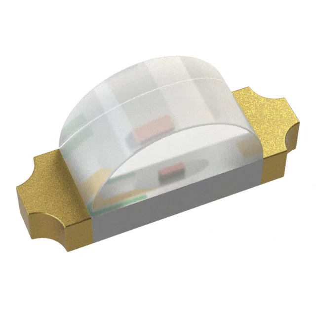
The ASMT-CR00 of red color chip-type LEDs is designed with the
smallest footprint to achieve high density of components on board.
They have the industry standard footprint 1.6 mm x 1.0 mm and a
height of only 0.4 mm. This makes them very suitable for cellular
phone and mobile equipment backlighting and indication
application where space is a constraint. In order to facilitate
automated pick and place operation, these ChipLEDs are shipped
in conductive tape and reel, with 4000 units per reel. These part
are compatible with IR soldering.
•
•
•
•
•
•
•
Small size right angle mount
0603 industry standard footprint
0.4 mm low profile type
Operating temperature range of -40oC to +85 oC
Compatible with IR reflow soldering process
Available in 8mm tape on 178mm (7’) diameter reels
Reel sealed in zip locked moisture barrier bags
Applications
•
•
•
•
LCD Backlighting
Keypad Side / Backlighting
Pushbutton backlighting
Symbol Indicator
Package Dimension
Device Selection Guide
Package Dimension (mm)
Parts per Reel
Package Description
1.6 (L) x 1.0 (W) x 0.4 (H)
4000
Untinted, Non-diffused
CAUTION: ASMT-CR00 LEDs are Class 1A ESD sensitive per JESD22-A114C.01. Please observe appropriate
precautions during handling and processing. Refer to Application Note AN-1142 for additional details.
1
�Absolute Maximum Ratings at TA = 25°C
Parameter
ASMT-CR00
Unit
DC Forward Current [1]
25
mA
Power Dissipation
60
mW
Reverse Voltage (IR = 100µA)
5
V
LED Junction Temperature
95
°C
Operating Temperature Range
-40 to +85
°C
Storage Temperature Range
-40 to +85
°C
Soldering Temperature
See reflow soldering profile (Figure 6 & 7)
Note:
1. Derate linearly as shown in Figure 4.
Electrical Characteristics at TA = 25°C
Forward Voltage
Reverse Breakdown
VF (Volts) [1]
VR (Volts)
Thermal Resistance
@ IF = 20mA
@ IR = 100µ
µA
Rθ
θJ-PIN (°C/W)
Part Number
Typ.
Max.
Min.
Typ.
ASMT-CR00
1.9
2.4
5
400
Notes:
1.Vf tolerance : ±0.1V
Optical Characteristics at TA = 25°C
Luminous Intensity
Peak
IV [1] (mcd)
Wavelength
Dominant
Wavelength
@ 20mA
λpeak (nm)
λd [2] (nm)
(Degrees)
Typ.
Typ.
Typ.
637.0
626.0
150
Part Number
Min.
Typ.
ASMT-CR00
28.5
90.0
Viewing Angle
2 θ1/2 [3]
Notes:
1. The luminous intensity IV is measured at the peak of the spatial radiation pattern which may not be aligned with the mechanical axis of
the LED package.
2. The dominant wavelength, λd, is derived from the CIE Chromaticity Diagram and represents the perceived color of the device.
3. θ1/2 is the off-axis angle where the luminous intensity is ½ the peak intensity.
2
�Light Intensity (IV) Bin Limits
Intensity (mcd)
Bin ID
Minimum
Minimum
N
28.50
45.00
P
45.00
71.50
Q
71.50
112.50
R
112.50
180.0
Notes:
1.
2.
Bin categories are established for classification
of products. Products may not be available in all
categories. Please contact your Avago
representative for information on current
available bins.
The Iv binning specification set-up is for lowest
allowable Iv binning only. There is no upper Iv
bin limits.
Tolerance : ±15%
Color Bin Limits
Dominant Wavelength (nm)
Bin ID
Minimum
Maximum
-
620.0
635.0
Tolerance : ±1nm
Figure 1. Relative intensity vs. wavelength
Figure 2. Forward current vs. forward voltage
3
�Figure 3. Luminous intensity vs. forward current
Figure 4. Maximum forward current vs. ambient temperature
EMITTING DIRECTION
Figure 5. Recommended soldering land pattern.
Notes:
1. All dimensions are in millimeters (inches).
2. Tolerance is ±0.1mm (±0.004in.) unless otherwise specified.
Figure 6. Recommended reflow soldering profile.
Figure 7. Recommended Pb-free reflow soldering profile.
4
�Figure 9. Reeling orientation.
Figure 10. Reel dimensions.
Notes:
1. All dimensions are in millimeters (inches).
2. Tolerance is ±0.1mm (±0.004in.) unless otherwise specified.
5
�TABLE 1
DIMENSIONS IN MILLIMETERS (INCHES)
DIM.A
DIM.B
DIM.C
PART NUMBER ± 0.10 (0.004) ± 0.10 (0.004) ± 0.10 (0.004)
ASMT-CR00
1.75 (0.069)
1.10 (0.043)
0.60 (0.024)
Figure 11. Tape dimensions.
Notes:
1. All dimensions are in millimeters (inches).
2. Tolerance is ±0.1mm (±0.004in.) unless otherwise specified.
Reflow Soldering:
For more information on reflow soldering,
refer to Application Note AN-1060, Surface
Mounting SMT LED Indicator
Components.
Storage Condition:
5 to 30°C @ 60%RH max.
Baking is required before mounting, if:
1. Humidity Indicator Card is > 10% when
read at 23 ± 5°C.
2. Device expose to factory conditions
很抱歉,暂时无法提供与“ASMT-CR00”相匹配的价格&库存,您可以联系我们找货
免费人工找货- 国内价格 香港价格
- 1+3.814081+0.49233
- 10+2.6227210+0.33854
- 100+1.86676100+0.24097