ASMT-FG10-NFJ00
Surface Mount AF Lamp
Data Sheet
Description
Features
Avago Technologies ASMT-FG10-NFJ00 is a SMT (Surface
Mount Technology) dome lamp uses an untinted, nondiffused lens to provide a high luminous intensity within a
narrow radiation pattern. The device is made by encapsulating LED chip on axial lead frame to form molded
epoxy lamp package with 6 bended leads for surfacing
mounting.
x Smooth, Consistent Narrow Radiation Pattern
This lamp type LED utilizes Indium Gallium Nitrate
(InGaN) material technology. The InGaN material has
a very high luminous efficiency, capable of producing
high light output over a wide range of drive currents.
The color available for this SMT Lamp package is 530nm
Green.
This narrow angle SMT lamp package is designed for applications that require long distance illumination and
narrow beam pattern such as auxiliary flash for auto-focus function in digital still camera etc. In order to facilitate pick and place operation, this SMT Lamp is shipped
in tape and reel, with 1000 units per reel.
This package is compatible with Pb-free 2x reflow
soldering process.
x 11° View Angle
x 4.8 L x 4.8 X 5.33H mm Package Dimension
x Good Intensity Output
x Compatible with 2x Solder Reflow
x Available in 16mm tape on 15inch (380mm) Diameter
reels
x Clear, Non-diffused Epoxy
x RoHS compliance
Applications
x Camera
Eye Safety
This LED is tested Class 1 to IEC/EN 60825-1 (2001) under
operation at 20mA. This LED is not recommended to
drive beyond 20mA as some of this LED might fall in the
classification of Class 2M to IEC/EN 60825-1 (2001).
CAUTION: ASMTFG10 LEDS ARE CLASS 1 ESD SENSITIVE. PLEASE OBSERVE APPROPRIATE PRECAUTIONS
DURING HANDLING AND PROCESSING. REFER TO AVAGO APPLICATION NOTE AN1142 FOR ADDITIONAL DETAILS.
�Package Dimensions
5.20 ± 0.1
1
4
2
5
3
6
Pin: 1,2,4 - Anode
Pin: 3,5,6 - Cathode
1.27
4.80 ± 0.1
0.51
4.80 ± 0.1
3.92
5.33 ± 0.1
Ø 4.32
0.15
Notes:
1. All Dimensions in millimeters.
2. Tolerance is ±0.1mm unless otherwise specified.
Device Selection Guide
Color
Part Number
Min. IV (cd)
Typ. IV (cd)
Max. IV (cd)
Test Current (mA)
Dice Technology
Green
ASMT-FG10-NFJ00
18
41
56
20
InGaN
Notes:
1. The luminous intensity IV, is measured at the mechanical axis of the lamp package. The actual peak of the spatial radiation pattern may not be
aligned with this axis.
2. Iv Tolerance = ±15%
2
�Absolute Maximum Ratings at TA = 25°C
Parameter
ASMT-FG10-NFJ00
Units
DC Forward Current
20
mA
Power Dissipation
80
mW
LED Junction Temperature
110
°C
Operating Temperature Range
-40 to +85
°C
Storage Temperature Range
-40 to +100
°C
Soldering Temperature
Refer to Figure 7
Electrical Characteristic (TA = 25°C)
Part Number
ASMT-FG10-NFJ00
Forward Voltage
VF [1](Volts) @ IF = 20mA
Reverse Voltage
VR @ 10PA
Capacitance
C (pF), VF= 0 f = 1MHz
Typ
Max
Min
Typ.
3.3
3.9
5
65
Notes:
1. VF will reach stabilization stage after switch on > 50ms
2. Vf tolerance is ±0.1V.
Optical Characteristics (TA = 25 °C)
Peak Wavelength
OPEAK (nm)
Dominant Wavelength OD [1] (nm)
Viewing Angle
2T½ [2] (Degrees)
Luminous Efficacy,
Kv[3] (lm/W)
Luminous
Efficiency (lm/W)
Part Number
Color
Typ.
Typ.
Typ.
Typ.
Typ
ASMT-FG10-NFJ00
Green
525
530
11
535
32
Notes:
1. The dominant wavelength, OD, is derived from the CIE Chromaticity Diagram and represents the color of the device.
2. T½ is the off-axis angle where the luminous intensity is ½ the peak intensity.
3. Radiant intensity, Ie in watts/steradian, may be calculated from the equation Ie = Iv/Kv, where Iv is the luminous intensity in candelas and Kv is
the luminous efficacy in lumens/watt.
Iv Bin Category
Bin ID
Min
Max
Green
Min (nm)
Max (nm)
F+
18.0
19.5
A
515.0
520.0
G
19.5
25.5
B
520.0
525.0
H
25.5
33.0
C
525.0
530.0
I
33.0
43.0
D
530.0
535.0
J
43.0
56.0
Iv Tolerance = ±15%
3
Color Bin Category
Tolerance = ±1nm
�FORWARD CURRENT - mA
RELATIVE INTENSITY
20
1
0.9
0.8
0.7
0.6
0.5
0.4
0.3
0.2
0.1
0
16
12
8
4
0
380
430
480
530
580
630
WAVELENGTH - nm
680
730
780
0
1
2.5
3
3.5
4
1
RELATIVE LUMINOUS INTENSITY
(Normalized at 20mA)
-1
-2
-3
-4
-5
0.8
0.6
0.4
0.2
0
-6
0
0.025
0.05
0.075
0.1
0.125
0
0.15
2
4
TIME - Sec
Figure 3. Vf stabilization vs time
6
8
10 12 14
DC FORWARD CURRENT - mA
16
18
Figure 4. Relative Intensity vs. Forward Current
1
0.9
0.8
0.7
0.6
0.5
0.4
0.3
0.2
0.1
0
25
MAXIMUM DC FORWARD CURRENT - mA
NORMALIZED INTENSITY
2
Figure 2. Forward Current vs Forward Voltage
0
20
15
10
5
0
-90
-60
-30
0
30
60
ANGULAR DISPLACEMENT - DEGREES
Figure 5. Radiation Pattern
4
1.5
FORWARD VOLTAGE - V
Figure 1. Relative Intensity vs. Wavelength
% VF SHIFT
0.5
90
0
20
40
60
AMBIENT TEMPERATURE - °C
80
Figure 6. Maximum forward current vs ambient temperature
100
20
�10 to 20 SEC.
217°C
TEMPERATURE
1.4
255-260°C
-6°C/SEC. MAX.
3°C/SEC. MAX.
200°C
0.6
150°C
0.67
3°C/SEC. MAX.
100 SEC. MAX.
60 - 120 SEC.
2.66
TIME
Figure 7. Recommended reflow soldering
Figure 8. Recommended soldering land pattern
USER FEED DIRECTION
CATHODE SIDE
1
4
2
5
Cathode Side
3
PRINTED LABEL
Figure 9. Reeling Orientations
Note: Cathode side is base on the center leads
Figure 10. Reel Dimensions
5
6
�12.00 ± 0.10
2.00 ± 0.10
Ø 1.50 ± 0.10
4.00 ± 0.10
1.75 ± 0.10
7.50 ± 0.10
16.00 + 0.30
- 0.10
Ø 1.50 ± 0.25
0.400 ± 0.02
6° MAX
10° MAX
5° MAX
5.34 ± 0.10
4.95 ± 0.10
A.
5.40 ± 0.10
B.
K.
Figure 11. Tape Dimensions
END
START
THERE SHALL BE A MINIMUM OF
600 mm (23.6 INCH) OF EMPTY
COMPONENT POCKETS SEALED
WITH COVER TAPE.
MOUNTED WITH
COMPONENTS
THERE SHALL BE A MINIMUM OF
160 mm (6.3 INCH) OF EMPTY
COMPONENT POCKETS SEALED
WITH COVER TAPE.
Figure 12. Tape Leader and Trailer Dimensions.
There shall be a minimum of 600mm (23.6”) of empty component pockets sealed with cover tape
Notes:
1. All dimensions in millimeters.
2. Tolerance is ± 0.1 mm unless otherwise specified.
6
MINIMUM OF 230 mm
(9.05 INCH) MAY
CONSIST OF CARRIER
AND/OR COVER TAPE.
�Handling Precaution
This products is classified as moisture sensitive level 3
When the bag is opened, parts required to mount within
168 hours of factory conditions ≤ 30 °C/60%, and stored
at 10% when read at
23±5°C
b) The pack has been opened for more than 168 hours.
Baking recommended condition: 60 ± 5°C for 20 hours.
Note:
1) Do not stack the units after reflow.
2) This part is Class 1 ESD sensitive. Please observe appropriate
precautions during handling and processing. Refer to Application
Note AN-1142 for additional details.
For product information and a complete list of distributors, please go to our web site:
www.avagotech.com
Avago, Avago Technologies, and the A logo are trademarks of Avago Technologies in the United States and other countries.
Data subject to change. Copyright © 2005-2010 Avago Technologies. All rights reserved. Obsoletes AV01-0695EN
AV02-2431EN - March 25, 2010
�
很抱歉,暂时无法提供与“ASMT-FG10-NFJ00”相匹配的价格&库存,您可以联系我们找货
免费人工找货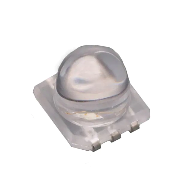


 工商网监
湘ICP备2023018690号
工商网监
湘ICP备2023018690号
