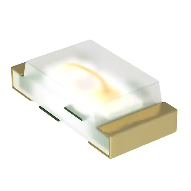
ASMT-Rx45-xxxxx
0.45mm Leadframe-Based Surface Mount ChipLED
Data Sheet
Description
Features
Avago’s ultra-thin ASMT-Rx45 ChipLEDs were developed
based on the industrial standard ChipLED 0603 platform
which requires less board space. These ChipLEDs provide
a wide viewing angle of 130 degrees to improve visibility
in bright sunlight.
• Industrial 0603 platform – 1.6 x 0.8 x 0.45mm
In addition to the high-brightness and compact size,
Avago’s ASMT-Rx45 ChipLEDs provide two significant
advantages in the production environment: They can
be easily soldered using IR solder reflow process, and
the package is qualified to a Joint Electronic Device Engineering Council (JEDEC) moisture sensitive level (MSL)
rating of 2a. For manufacturers, this rating means that
these ChipLEDs can be kept in the open air (30 degrees
C, 60 percent relative humidity) for up to four weeks after
being removed from its sealed package without the need
to remove absorbed moisture.
• Robust Operating Temperature from - 40 to +100°C
Avago’s ultra-thin Leadframe ChipLED available in Red,
Orange, Yellow Green and Amber colors, the ASMT-Rx45
series is ideal for use by lighting designers developing
backlighting for dashboards and entertainment consoles
in automobiles, backlighting of industrial switches and
buttons, and small pixel indoor signs.
• Automotive qualified
• Super wide 145 deg viewing angle
• JEDEC MSL 2a.
• Junction Temperature Tj = 110°C
• Available in 4000 parts per reel
• RoHS & IR Reflow compatible
Applications
• Interior Automotive
– Navigation backlighting
– Audio panel backlighting
– Push Button backlighting
• Office Automation, home appliances, industrial
equipment
– Front panel backlighting
– Push Button backlighting
– LCD backlighting
– Switches backlighting
– Navigation backlighting
CAUTION: ASMT-Rx45 LEDs are Class 1C ESD sensitive per JESD22-A114C.01. Please observe appropriate
precautions during handling and processing. Refer to Application Note AN-1142 for additional details.
�Package Dimensions
0.45
0.4
1.1
1.6
LED Die
Cathode
Side
Lead
Frame
0.6
0.8
Resin
NOTES:
1. All Dimensions in millimeters.
2. Tolerance is ± 0.1mm unless otherwise specified.
Device Selection Guide
Part Number
Min. Iv
(mcd)
Typ. Iv
(mcd)
Test Current
(mA)
Colors
Dice Technology
Package Description
ASMT-RR45-AQ902
90.0
120.0
20
Red
AlInGaP
Untinted, Diffused
ASMT-RJ45-AQ502
71.5
130.0
20
Orange
AlInGaP
Untinted, Diffused
ASMT-RF45-AN002
28.0
60.0
20
Yellow Green
AlInGaP
Untinted, Diffused
ASMT-RA45-AP932
57.0
90.0
20
Amber
AlInGaP
Untinted, Diffused
ASMT-RH45-AQ502
71.5
110.0
20
Red Orange
AlInGaP
Untinted, Diffused
Notes:
1. The luminous intensity IV is measured at the peak of the spatial radiation pattern which may not be aligned with the mechanical axis of the LED
package.
2. Tolerance: ±15%
Part Numbering System
A S M T - R X1 45 - X2 X3 X4 X5 X6
Packaging Option
Color Bin Selection
Max. Intensity Bin
Min. Intensity Bin
LED Chip Color
2
�Absolute Maximum Ratings at TA = 25°C
Parameter
ASMT-Rx45
Units
DC Forward Current [1]
20
mA
Power Dissipation
48
mW
Reverse Voltage (IR = 100mA)
5
V
LED Junction Temperature
110
°C
Operating Temperature Range
-40 to +100
°C
Storage Temperature Range
-40 to +100
°C
Notes:
1. Applies when single LED is lit up.
Electrical Characteristics at TA = 25°C
Forward Voltage, VF (Volts) [1]
@ IF = 20mA
Reverse Breakdown
VR (Volts) @ IR = 100µA
Thermal Resistance
RθJ-PIN (°C/W)
Part Number
Min.
Typ.
Max.
Min.
Typical
ASMT-Rx45-Axxxx
1.6
2.0
2.4
5
246
Notes:
1. VF Tolerance: ±0.1V
Optical Characteristics at TA = 25°C
Peak Wavelength
λpeak (nm)
Dominant Wavelength
λd [2] (nm)
Viewing Angle
2θ1/2[3] (Degrees)
Part Number
Color
Typical
Typical
Typical
ASMT-RR45-AQ902
Red
636
622
145
ASMT-RJ45-AQ502
Orange
612
605
145
ASMT-RF45-AN002
Yellow Green
574
573
145
ASMT-RA45-AP932
Amber
593
591
145
ASMT-RH45-AQ502
Red Orange
621
615
145
Notes:
1. The dominant wavelength, λd, is derived from the CIE Chromaticity Diagram and represents the perceived color of the device.
2. θ1/2 is the off-axis angle where the luminous intensity is ½ the peak intensity.
3
�1
AMBER
0.9
RED
YELLOW
GREEN
0.7
IF - FORWARD CURRENT - mA
RELATIVE INTENSITY
0.8
100
ORANGE
0.6
0.5
0.4
0.3
0.2
AMBER/
ORANGE
RED
10
YELLOW
GREEN
0.1
0
380
430
480
530
580
630
WAVELENGTH-nm
680
730
1
0.00
780
3.00
MAX. FORWARD CURRENT - mA
1.20
1.00
0.80
0.60
0.40
0.20
0
5
10
15
20
IF - FORWARD CURRENT - mA
25
30
Figure 3. Luminous intensity vs. forward current
20
15
10
5
0
0
20
40
60
80
AMBIENT TEMPERATURE - °C
100
Figure 4. Maximum forward current vs. ambient temperature.
Derated based on TJMAX = 110°C, RqJA = 465°C/W
1.0
RELATIVE INTENSITY
0.9
0.8
0.7
0.6
0.8
(0.031)
0.5
0.4
0.3
0.2
0.1
0.0
-90 -80 -70 -60 -50 -40 -30 -20 -10 0 10 20 30 40 50 60 70 80 90
ANGLE
Figure 5. Radiation pattern
0.8
0.7
0.8
(0.031) (0.028) (0.031)
Figure 6. Recommended soldering land pattern
Notes:
1. All dimensions are in millimeters (inches).
2. Tolerance is ±0.1mm (±0.004in.) unless otherwise specified.
4
3.50
25
1.40
RELATIVE LUMINOUS INTENSITY
(NORMALIZED AT 20mA)
1.00
1.50
2.00
2.50
V F - FORWARD VOLTAGE - V
Figure 2. Forward current vs. forward voltage
Figure 1. Relative intensity vs. wavelength
0.00
0.50
120
�10 to 30 SEC.
10 SEC. MAX.
4ºC/SEC. MAX.
140-160
-3ºC/SEC.
MAX.
4ºC/SEC.
MAX.
TEMPERATURE
TEMPERATURE
230ºC/ MAX.
217ºC
200ºC
255 - 260ºC
3ºC/SEC. MAX.
6ºC/SEC. MAX.
150ºC
3ºC/SEC. MAX.
100 SEC. MAX.
60 - 120 SEC.
OVER 2 MIN.
TIME
TIME
(Acc. to J-STD-020C)
Figure 7b. Recommended Pb-free reflow soldering profile
Figure 7a. Recommended reflow soldering profile
Notes:
For detail information on reflow soldering of Avago surface mount LEDs, do refer to Avago Application Note AN 1060 Surface Mounting SMT LED
Indicator Components.
4.00
DIM. C
[0.157]
[SEE TABLE 1]
1.50
0.254 +/- 0.02
[0.059]
4.00
[0.01 +/- 0.001]
[0.157]
1.75
[0.069]
3.50 +/- 0.05
[0.14 +/- 0.002]
DIM. A
8.00 +/- 0.30
[0.315 +/- 0.012]
[SEE TABLE]
DIM. B
USER FEED
DIRECTION
[SEE TABLE]
Figure 8. Tape Dimensions
USER FEED DIRECTION
CATHODE SIDE
PRINTED LABEL
Figure 9. Reeling Orientation
5
CARRIER TAPE
Diam. 0.60 +/- 0.05
COVER TAPE
�Intensity Bin Select (X3X4)
Light Intensity (IV ) Bin Limits
Individual reel will contain parts from one half bin only
X3
Min IV Bin
X4
Intensity (mcd)
Bin ID
Min.
Max.
A1
0.11
0.14
A2
0.14
0.18
0
Full Distribution
B1
0.18
0.23
2
2 half bins starting from X31
B2
0.23
0.29
3
3 half bins starting from X31
C1
0.29
0.36
4
4 half bins starting from X31
C2
0.36
0.45
5
5 half bins starting from X31
D1
0.45
0.57
6
2 half bins starting from X32
D2
0.57
0.72
7
3 half bins starting from X32
E1
0.72
0.90
8
4 half bins starting from X32
E2
0.90
1.10
9
5 half bins starting from X32
F1
1.10
1.41
F2
1.41
1.80
G1
1.80
2.24
G2
2.24
2.80
H1
2.80
3.55
H2
3.55
4.50
J1
4.50
5.70
J2
5.70
7.20
K1
7.20
9.00
K2
9.00
11.20
L1
11.20
14.20
L2
14.20
18.00
M1
18.00
22.50
M2
22.50
28.00
N1
28.00
36.00
N2
36.00
45.00
P1
45.00
57.00
P2
57.00
71.50
Q1
71.50
90.00
Q2
90.00
113.00
R1
113.00
142.00
R2
142.00
180.00
S1
180.00
227.00
S2
227.00
285.00
Tolerance: ±15%
6
�Color Bin Select (X5)
Color Bin Limits
Individual reel will contain parts from one full bin only.
Yellow Green Color Bin
Dominant Wavelength (nm)
X5
0
Full Distribution
Bin ID
Min.
Max.
564.5
567.5
Z
A and B only
E
Y
B and C only
F
567.5
570.5
W
C and D only
G
570.5
573.5
V
D and E only
H
573.5
576.5
U
E and F only
T
F and G only
S
G and H only
Q
Yellow/Amber Color Bin
Dominant Wavelength (nm)
A, B and C only
Bin ID
Min.
Max.
P
B, C and D only
A
582.0
584.5
N
C, D and E only
B
584.5
587.0
M
D, E and F only
C
587.0
589.5
L
E, F and G only
D
589.5
592.0
K
F, G and H only
E
592.0
594.5
J
Special Color Bin
F
594.5
597.0
1
A, B, C and D only
2
E, F, G and H only
3
B, C, D and E only
4
C, D, E and F only
5
A, B, C, D and E only
6
B, C, D, E, and F only
Orange Color Bin
Dominant Wavelength (nm)
Packaging Option (X6)
Option
Test Current
Package Type
Reel Size
2
20 mA
Top Mount
7 Inch
H
2 mA
Top Mount
7 Inch
K
5 mA
Top Mount
7 Inch
Forward Voltage (VF) Bin Limits
Bin ID
Min
Max
A
597.0
600.0
B
600.0
603.0
C
603.0
606.0
D
606.0
609.0
E
609.0
612.0
Red Color Bin
Dominant Wavelength (nm)
Bin ID
Min.
Max.
Full Distribution
620.0
635.0
Red Orange Color Bin
Forward Voltage (V)
Minimum
Maximum
Bin ID
Min.
Max.
1
1.60
1.80
A
610.0
615.0
2
1.80
2.00
B
615.0
620.0
3
2.00
2.20
4
2.20
2.40
Tolerance: ±0.1V
7
Dominant Wavelength (nm)
Bin ID
Tolerance: ±1nm
�Moisture Sensitivity
This product is qualified as Moisture Sensitive Level 2a per Jedec J-STD-020. Precautions when handling this moisture
sensitive product is important to ensure the reliability of the product. Do refer to Avago Application Note AN5305
Handling of Moisture Sensitive Surface Mount Devices for details.
A. Storage before use
– Unopen moisture barrier bag (MBB) can be stored at
很抱歉,暂时无法提供与“ASMT-RJ45-AQ502”相匹配的价格&库存,您可以联系我们找货
免费人工找货- 国内价格 香港价格
- 1+4.239031+0.54794
- 10+2.9406310+0.38011
- 100+2.10062100+0.27153
- 500+1.72432500+0.22289
- 1000+1.600181000+0.20684
- 2000+1.494662000+0.19320
- 国内价格 香港价格
- 4000+1.404974000+0.18161
- 8000+1.328898000+0.17178
- 12000+1.2898912000+0.16673
- 20000+1.2458420000+0.16104
- 28000+1.2196428000+0.15765
- 40000+1.1940940000+0.15435