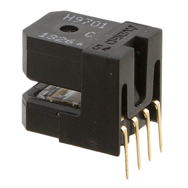
HEDS-5500, HEDS-6500 and HEDS-9000, 9100, 9200 Series
Motion Sensing Products, Optical Encoder Modules
Reliability Data
Description
The following cumulative test results have been obtained from testing performed at Avago Technologies in accordance with the latest revision of MIL- STD-883. Avago tests parts at the absolute maximum rated conditions recommended for the device. The actual performance you obtain from Avago parts depends on the electrical and environmental characteristics of your application but will probably be better than the performance outlined in Table �.
Failure Rate Prediction
The failure rate of semiconductor devices is determined by the junction temperature of the device. The relationship between ambient temperature and actual junction temperature is given by the following: TJ (°C) = TA (°C) + θJA PAVG where TA = ambient temperature in °C θJA = thermal resistance of junction-to-ambient in °C/watt PAVG = average power dissipated in watts The estimated MTBF and failure rate at temperatures lower than the actual stress temperature can be determined by using an Arrhenius model for temperature acceleration. Results of such calculations are shown in the table on the following page using an activation energy of 0.43 eV (reference MIL-HDBK-2�7).
Table 1. Life Tests
Demonstrated Performance
Point Typical Performance Test Name High Temperature Operating Life Stress Test Conditions VCC = 5.5 V, VA = VB = 3.5 V TA = �00°C �000 hours VCC = 5.5 V VA = VB = 3.5 V �,000 hours TA = 85°C RH = 85% Total Device Hrs. �,405,000 Units Tested �,405 Total Failed 2 MTBF 702,500 Failure Rate (% /1K Hours) 0.�42
Temperature Humidity Operating Life
�,495,000
�,495
�0
�49,500
0.669
�
�Table 2.
Point Typical Performance [1] in Time Ambient Temperature (°C) +�00 +90 +80 +70 +60 +50 +40 +30 +20 Junction Temperature (°C) +��0 +�00 +90 +80 +70 +60 +50 +40 +30 MTBF [1] 703,000 996,000 �,440,000 2,�26,000 3,2�0,000 4,968,000 7,90�,000 �2,942,000 2�,903,000 Failure Rate (%/1K Hours) 0.�42 0.�00 0.069 0.047 0.03� 0.020 0.0�3 0.008 0.005 Performance in Time [2] (90% Confidence) MTBF [2] 264,000 374,000 54�,000 799,000 �,206,000 �,867,000 2,969,000 4,863,000 8,230,000 Failure Rate (%/1K Hours) 0.379 0.267 0.�85 0.�25 0.083 0.054 0.034 0.02� 0.0�2
Notes: �. The point typical MTBF (which represents 60% confidence level) is the total device hours divided by the number of failures. In the case of zero failures, one failure is assumed for this calculation. 2. The 90% Confidence MTBF represents the minimum level of reliability performance which is expected from 90% of all samples. This confidence interval is based on the statistics of the distribution of failures. The assumed distribution of failures is exponential. This particular distribution is commonly used in describing useful life failures. Refer to MIL-STD-690B for details on this methodology. 3. Failures are catastrophic or parametric. Catastrophic failures are open, short, no logic output, no dynamic parameters while parametric failures are failures to meet an electrical characteristic as specified in product catalog such as output voltage, duty or state errors.
Example of Failure Rate Calculation Assume a device operating 8 hours/day, 5 days/week. The utilization factor, given �68 hours/week is: (8 hours/day) x (5 days/week) / (�68 hours/week) = 0.25 The point failure rate per year (8760 hours) at 50°C ambient temperature is: (0.020% / �K hours) x 0.25 x (8760 hours/year) = 0.044% per year Similarly, 90% confidence level failure rate per year at 50°C: (0.054% / �K hours) x 0.25 x (8760 hours/year) = 0.��8% per year
2
�Table 3. Environmental Tests
Test Name Temperature Cycle MIL-STD-883C Reference �0�0 Test Conditions -40°C to +�00°C, �5 minute dwell, 5 minute transfer, 5 cycles 200 cycles 500 cycles Sn/Pb 60/40 Solder; 260°C peak; �0 sec., 20 temp cycles @ -40°C to 85°C TA = +�05°C 2,000 hours Units Tested Units Failed
9,5�2 �,570 �,570 38 77
0 3 9 0 0
Solder Heat Resistance High Temperature Storage Life
2003 N/A
Table 4. Mechanical Tests
Test Name Mechanical Shock Vibration Variable Frequency MIL-STD-883C Reference 2002 2007 Test Conditions 5 blows; X, Y, Z axes, �500 g, 0.5 msec. 3 cycles, 4 min. each X, Y, Z axes, 20 g min. 20 to 2000 Hz 5 to �000 Hz 3 bends, �5° minimum Units Tested 5 26 �0 �5 �5 Units Failed 0 0 0 0 0
Terminal Strength Lead Fatigue
2004 Condition A � lb. for 30 seconds 2004, Cond. B
Table 5. Electrical Tests
Test Name ESD - Human Body Model MIL-STD-883C Reference 30�5.2 Test Conditions �.5 KΩ, �00 pF, 5 positive and 5 negative discharges per pin. VZ = 3.0 KV Units Tested 35 Units Failed 0
3
�For product information and a complete list of distributors, please go to our web site:
www.avagotech.com
Avago, Avago Technologies, and the A logo are trademarks of Avago Technologies, Limited in the United States and other countries. Data subject to change. Copyright © 2006 Avago Technologies Limited. All rights reserved. Obsoletes 5965-2775E 5965-9642E - December 11, 2006
4
�