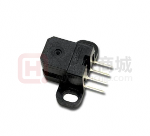
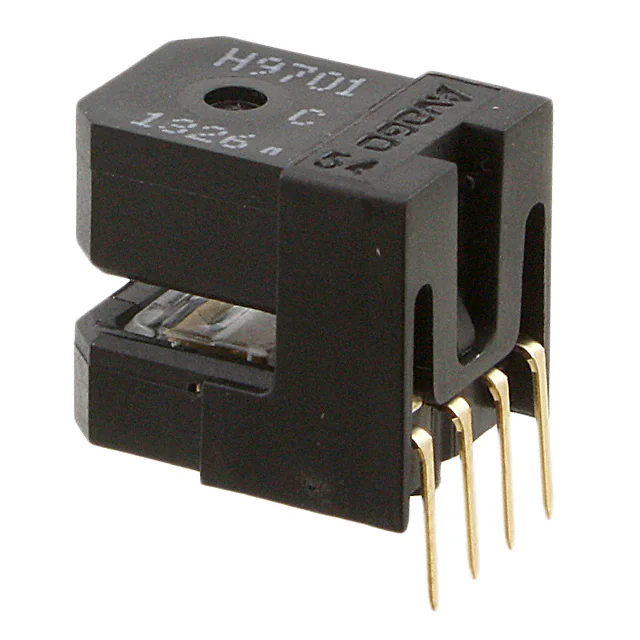
HEDS-9731

HEDS-9731

  • 厂商:

    AVAGO(博通)

  • 封装:

  • 描述:

    HEDS-9731 - Small Optical Encoder Modules 480lpi Digital Output - AVAGO TECHNOLOGIES LIMITED

  • 详情介绍
  • 数据手册
  • 价格&库存
HEDS-9731 数据手册
HEDS-9730, HEDS-9731 Small Optical Encoder Modules 480lpi Digital Output Data Sheet Description The HEDS-973X is a high performance incremental encoder module. When operated in conjunction with either a codewheel or codestrip, this module detects rotary or linear position. The encoder consists of a lensed LED source and a detector IC enclosed in a small Cshaped plastic package. Due to a highly collimated light source and a unique photodetector array, the module is extremely tolerant to mounting misalignment. The two channel digital outputs and 3.3V supply input are accessed through four solder plated leads located on 2.54mm (0.1inch) centers. The standard HEDS-973X is designed for use with an appropriate optical radius codewheel or linear codestrip. Other options are available. Please contact the factory for more information. Features • Small Size • High Resolution • Two Channel Quadrature Output • Linear and Rotary Applications • No Signal Adjustment required • T TL or 3.3V/5V CMOS Compatible • Wave Solderable • Lead-free Package • -40°C to 85°C Operating Temperature • Single 3.3V Supply Applications The HEDS-973X provides sophisticated motion detection, making closed loop control very cost competitive. Typical applications include printers, plotters, copiers and office automation equipment. Note: Avago Technologies’ encoders are not recommended for use in safety critical applications, e.g., ABS braking systems and critical-care medical equipment. Please contact a sales representative if more clarification is needed. Block Diagram RESISTOR LENS PHOTODIODES COMPARATORS A + AB + VCC 3 CHANNEL A 2 CHANNEL B 4 LED BSIGNAL PROCESSING CIRCUITRY GND 1 EMITTER SECTION CODE WHEEL DETECTOR SECTION Figure 1 ESD WARNING: NORMAL HANDLING PRECAUTIONS SHOULD BE TAKEN TO AVOID STATIC DISCHARGE.  Theory of Operation A HEDS-973X is a C-shaped emitter/detector module. Coupled with a codewheel, it translates rotary motion into a two-channel digital output; coupled with a codestrip, it translates linear motion into digital outputs. As seen in Figure 1, the module contains a single Light Emitting Diode (LED) as its light source. The light is collimated into parallel beam by means of a single lens located directly over the LED. Opposite the emitter is the integrated detector circuit. This IC consists of photodetectors and a signal processing circuitry necessary to produce the digital waveforms. The codewheel/codestrip moves between the emitter and detector, causing the light beam to be interrupted by the pattern of spaces and bars on the codewheel/ codestrip. The photodiodes, which detect these interruptions, are arranged in a pattern that corresponds to the radius and count density of the codewheel/ codestrip. These photodiodes are also spaced such that a light period on one pair of detectors corresponds to a dark period on the adjacent pairs of detectors. The photodiode outputs are fed through the signal processing circuitry. Two comparators receive these signal and produce the final outputs for Channels A and B. Due to this integrated phasing technique the output of channel A is in quadrature with Channel B (90 degrees out of phase). Definitions Note: Refer to Figure 2 Count (N): The number of bar and window pairs or counts per revolution (CPR) of the codewheel. Or the number of lines per inch of the codestrip (LPI) 1 shaft Rotation = 360 degrees = N cycles 1 cycle (c) = 360 electrical degree, equivalent to 1 bar and window pair. Pulse Width (P): The number of electrical degrees that an output is high during one cycle, nominally 180°e or 1/2 a cycle. Pulse Width Error (DP): The deviation in electrical degrees of the pulse width from its ideal value of 180°e. State Width (S): The number of electrical degrees between a transition in the output of channel A and the neighboring transition in the output of channel B. There are 4 states per cycle, each nominally 90°e. State Width Error (DS): The deviation in electrical degrees of each state width from its ideal value of 90°e. Phase (f): The number of electrical degrees between the center of the high state on channel A and the center of the high state on channel B. This value is nominally 90°e for quadrature output. Phase Error (Df): The deviation in electrical degrees of the phase from its ideal value of 90°e. Direction of Rotation: When the codewheel rotates in the counter-clockwise direction (as viewed from the encoder end of the motor), channel A will lead channel B. If the codewheel rotates in the clockwise direction, channel B will lead channel A. Optical Radius (Rop): The distance from the codewheel’s center of rotation to the optical center (O°C) of the encoder module. Angular Misalignment Error (EA): Angular misalignment of the sensor in relation to then tangential direction. This applies for both rotary and linear motion. Mounting Position (RM): Distance from Motor Shaft center of rotation to center of Alignment Tab receiving hole. Output Waveforms Figure 2.  Absolute Maximum Ratings Parameter Storage Temperature Operating Temperature Supply Voltage Output Voltage Output Current per Channel Soldering Temperature Symbol TS TA VCC VO IOUT TSOL Min. -40 -40 -0.5 -0.5 -.5 0 Max. 85 85 7 VCC 9 60 Units °C °C Volts Volts mA °C t* 5 sec Notes Recommended Operating Conditions Parameter Temperature Supply Voltage Load Capacitance Pull-up Resistor Frequency Angular Misalignment Mounting Position Symbol TA VCC CL RL f EA RM -.0 0.0 ROP-0.4 (ROP -0.006) none 40 +.0 kHz Deg. Min. -40 .8 . or 5 Typ. Max. 85 5. 00 Units °C Volts pF Recommend no pullup. Device has integrated .5 kW on outputs Velocity (rpm) x N/60 Refer to Mounting Consideration Ripple < 00mVp-p Notes Mm (inch) Refer to Mounting Consideration Electrical Characteristics Electrical Characteristics Over the Recommended Operating Conditions. Typical Values at 25°C. Parameter Supply Current High Level Output Voltage Low Level Output Voltage Rise Time Fall Time Symbol ICC VOH VOL tr tf 00 50 Min.  .4 Typ. 5 55 Max. 40 85 Volts Units mA Notes Typ. .V Typ. 5V When VOH = .4V (Min)Typ. IOH = -0.4 mA @ .VTyp. IOH = -.0 mA @ 5V When VOL = 0.4V (Max)Typ. IOL =  mA @ .VTyp. IOL = 4 mA @ 5V CL=25 pF 0.4 Volts ns ns Encoding Characteristics Encoding Characteristics Over the Recommended Operating Conditions and Mounting Conditions These characteristics do not include codewheel/codestrip contribution. The typical values are average over the full rotation of the codewheel Parameter Pulse Width Error State Width Error Phase Error Symbol DP DS Df Typical 5   Maximum 50 50 5 Units °e °e °e Notes  Mounting Considerations 5.32 MAX. (0.209) 4.40 ± 0.13 0.17 ± 0.005 SEE NOTE 1 Rm IMAGE SIDE OF CODEWHEEL/CODESTRIP Rop C OF ALIGNMENT TAB L 6.30 MAX. (0.248) 6.50 MIN. (0.256) CENTER OF ROTATION MOTOR SHAFT CENTER -A- 2.03 MIN. (0.080) 1.0 DEEP MIN. (0.039) 2X R EA Rm = Rop - 0.14 (0.006) ALIGNMENT TAB RECEIVING HOLE � 2.03 HOLE MIN. (0.080) 1.0 DEEP MIN. (0.039) A 0.13 mm (0.005") DIMENSIONS IN MILLIMETERS (INCHES). Note: These dimensions include shaft end play and codewheel warp. For both rotary and linear motion, angular misalignment, EA must be * ± 1 degrees to achieve Encoding Characteristics. All dimension for mounting the module and codewheel/codestrip should be measured with respect to two mounting posts, as shown above Recommended Codewheel and Codestrip Characteristics MAX 3.4 (0.134) Wb Lw Ww Rc Rop W1 W2 Ww Wb L Parameter Window/bar Ratio Window Length (Rotary) Absolute Maximum Codewheel Radius (Rotary) Center of Post to Inside Edge of Window Center of Post to Outside Edge of Window Center of Post to Inside Edge of Codestrip Symbol Ww/Wb LW Rc W W L Min. 0.9 .80 (0.07) Max. . . (0.09) Rop + .40 (Rop + 0.4) Unit mm (inch) mm (inch) mm (inch) mm (inch) Notes Includes eccentricity errors .04 (0.04) 0.76 (0.06) .60 (0.4) mm (inch) 4 Ordering Information HEDS - 973 Option Resolution 3 - 480 LPI Bracket Option 50 Lead Configurations 0 - Straight leads 1 - Bent leads Package Dimension Option 50 LEAD THICKNESS = 0.25 mm LEAD PITCH = 2.54 mm 3.8 0.5 5.5 ± 0.3 1.4 6.4 3.9 0.8 4.2 7.5 10.1 3.90 ± 0.10 1.70 ± 0.15 PART # (REFER -05) 5.0 4.2 R 1.4 R 2.6 3.0 OPTION CODE AVAGO XXXXX X 10.8 ± 0.5 CH B CH A GND V CC PIN 1 ID 7.0 12.6 ± 0.5 50 8.7 0.14 (OPTICAL CENTER) 2x ∅ 2.00 ± 0.02 C 8.4 15.0 YYWW DATE CODE C = COUNTRY OF ORIGIN MARKING (REFER -05 FOR DETAILS) 1.8 20.2 ± 0.5 9.8 Bent Version - Option 50 LEAD THICKNESS = 0.25 mm LEAD PITCH = 2.54 mm R 2.6 1.4 6.4 3.9 0.8 4.2 7.5 10.1 3.90 ± 0.10 1.8 1.70 ± 0.15 PART # (REFER -05) 5.0 R 1.4 6.0 3.0 ± 0.3 CH B CH A GND V CC 5° TYP. OPTION CODE PIN 1 ID 7.0 12.6 ± 0.5 8.7 9.2 ± 0.3 AVAGO XXXXX 4.2 X C 8.4 15.0 20.2 ± 0.5 0.14 (OPTICAL CENTER) 2x ∅ 2.00 ± 0.02 YYWW 50 DATE CODE C = COUNTRY OF ORIGIN MARKING (REFER -05 FOR DETAILS) 3.8 0.5 10.8 ± 0.5 9.8 5 Wave Soldering Profile 7 sec MAX. 260°C Y- AXIS FLOW 120° C/20 sec MAX. X- AXIS COOL DOWN Parameter A B C D E Solder Pot Temperature Preheat Zone Temperature Dip in Time Solder Pot Zone (PCB Top) Solder Pot Zone (Encoder Lead) Min. NA 85 5 NA 00 Max. 60 0 7 NA NA Nominal values 50 - 60 00 - 0 5 NA ≥ 00 Units °C °C sec °C °C For product information and a complete list of distributors, please go to our web site: www.avagotech.com Avago, Avago Technologies, and the A logo are trademarks of Avago Technologies Limited in the United States and other countries. Data subject to change. Copyright © 008 Avago Technologies Limited. All rights reserved. Obsoletes 5989-087EN AV0-057EN - February , 008
HEDS-9731
### 物料型号 - HEDS-9730 和 HEDS-9731

### 器件简介 - HEDS-973X是一款高性能增量式编码器模块,与码盘或码条配合使用时,能够检测旋转或线性位置。编码器由一个带有透镜的LED光源和一个封装在小型C形塑料外壳内的检测IC组成。由于具有高准直光源和独特的光电探测器阵列,该模块对安装误差具有极高的容忍度。

### 引脚分配 - 两个通道的数字输出和3.3V供电输入通过四个焊盘引脚实现,引脚间距为2.54mm(0.1英寸)。

### 参数特性 - 绝对最大额定值: - 存储温度:-40°C至85°C - 工作温度:-40°C至85°C - 供电电压:-0.5至7V - 输出电压:-0.5V至VCC - 每通道输出电流:-1.5至19mA - 焊接温度:20°C至260°C,持续5秒

- 推荐工作条件: - 温度:-40°C至85°C - 供电电压:2.8V至3.3V或5V,纹波<100mVp-p - 负载电容:100pF - 推荐不使用上拉电阻,设备有集成的2.5kW输出

- 电气特性(典型值在25°C时): - 供电电流:12mA至40mA(3.3V时),55mA至85mA(5V时) - 高电平输出电压:2.4V - 低电平输出电压:0.4V - 上升时间:200ns(负载电容25pF) - 下降时间:50ns

### 功能详解 - HEDS-973X是一个C形发射器/探测器模块,与码盘配合使用时,将旋转运动转换为双通道数字输出;与码条配合使用时,将线性运动转换为数字输出。模块包含一个LED作为光源,光线通过位于LED正上方的单个透镜准直成平行光束。对面是集成的探测器电路,包括光电探测器和产生数字波形所需的信号处理电路。

### 应用信息 - HEDS-973X提供复杂的运动检测,使得闭环控制具有很高的成本效益。典型应用包括打印机、绘图仪、复印机和办公自动化设备。

### 封装信息 - 封装选项50,引脚厚度为0.25mm,引脚间距为2.54mm。

HEDS-9731 价格&库存

很抱歉,暂时无法提供与“HEDS-9731”相匹配的价格&库存,您可以联系我们找货

免费人工找货
HEDS-9720#L50
  •  国内价格
  • 1+44.94463
  • 10+43.28002
  • 100+38.28617
  • 500+37.2874

库存:0

HEDS-9701#C54
  •  国内价格
  • 1+25.73999
  • 10+23.76
  • 30+23.364

库存:0