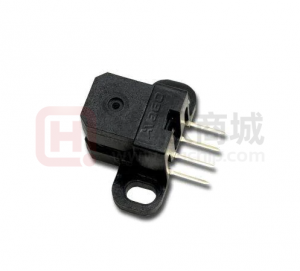
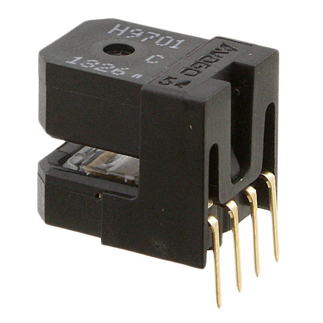
HEDS-97EX Series
Small Optical Encoder Modules 200 LPI Analog Voltage Output
Data Sheet
Description
The HEDS-97EX series is a small and high performance optical incremental encoder module. When operated in conjunction with either a codewheel or codestrip, this module detects rotary or linear position. The encoder module consists of a lensed LED source and a detector IC enclosed in a small C-shaped plastic package. Due to a highly collimated light source and a unique photodetector array, the module is extremely tolerant to mounting misalignment. The two channel analog outputs and 3.3V supply input are accessed through four solder-plated leads located on 2.54 mm (0.1 inch.) centers. HEDS-97EX is designed for use with an appropriate optical radius codewheel. Please contact factory for more information.
Features
• Small size • Multiple mounting options • Insensitive to radial and axial play • 0°C to +60°C recommended operating temperature • Two channel analog output • Single 3.3V supply • Wave solderable • RoHS compliant
Specifications
• 200 LPI • 3.3V supply* * Typical conditions
Applications
• Printers • Copiers/Fax • Plotters • Office automation equipments
ESD WARNING: NORMAL PRECAUTIONS SHOULD BE TAKEN TO AVOID STATIC DISCHARGE.
�
�Theory of Operation
The HEDS-97EX is a C-shaped emitter/detector module. Coupled with a codewheel/codestrip, it translates rotary motion into a two-channel analog output. The module contains a single Light Emitting Diode (LED) as its light source. The light is collimated into a parallel beam by means of a single lens located directly over the LED. Opposite the emitter is the integrated detector circuit. This IC consists of multiple sets of photodetectors and the signal processing circuitry necessary to produce the analog waveforms. The codewheel/codestrip moves between the emitter and detector, causing the light beam to be interrupted by the pattern of spaces and bars on the codewheel/ codestrip. The photodiodes, which detect these interruptions, are arranged in a pattern that corresponds to the radius and count density of the codewheel/codestrip. These detectors are also spaced such that a light period on one pair of detectors corresponds to a dark period on the adjacent pairs of detectors. The photodiode outputs are fed through the signal processing circuitry, which produce the final outputs for Channel A and Channel B. Due to this integrated phasing technique, the analog output of Channel A is in quadrature with Channel B (90 degrees out of phase).
Definitions
Count (N): The number of bar and window pairs or counts per revolution (CPR) of the codewheel. Or the number of lines per inch of the codestrip (LPI) 1 shaft rotation = 360 degrees = N cycles 1 cycle (c) = 360 electrical degree, equivalent to 1 bar and window pair.
Direction of Rotation: When the codewheel rotates in the counter-clockwise direction (as viewed from the encoder end of the motor), channel A will lead channel B. If the codewheel rotates in the clockwise direction, channel B will lead channel A. Line Density: The number of window and bar pair per unit length, express in either lines per inch (LPI) or lines per mm (LPmm) Optical Radius (Rop): The distance from the codewheel’s center of rotation to the optical center (O.C) of the encoder module. Gap (G): The distance from surface of the encoder to the surface of codewheel or codestrip Mounting Position (RM): Distance from Motor Shaft center of rotation to center of Alignment Tab receiving hole. Radial and Tangential Misalignment Error (ER and Er): For rotary motion mechanical displacement in the radial and tangential directions relative to the nominal alignment Angular Misalignment Error (EA): Angular misalignment of the sensor in relation to then tangential direction. This applies for both rotary and linear motion.of electrical degrees that an output is high during one cycle, nominally 180°e or 1/2 a cycle.
2
�Absolute Maximum Ratings
Subjecting the part to stresses beyond those listed under this section may cause permanent damage to the device. These are stress ratings only and do not imply that the device functions beyond these ratings. Exposure to the extremes of these conditions for extended periods may affect device reliability. Parameter Storage Temperature Operating Temperature Supply voltage (Detector) Output Voltage Soldering Temperature DC Forward current (LED) Reverse Voltage ILED VR Symbol TS TA VCC Va , Vb Min. -40 0 -0.5 -0.5 Max. 85 60 7 VCC + 0.4 260 50 5 Units °C °C V V °C mA V t ≤ 7 sec VF < �.8V IR = �00uA Notes
Recommended Operating Conditions
Parameter Operating Temperature Supply Voltage (Detector) Output Frequency DC Forward Current (LED) Symbol T VCC f ILED Min. 0 �.�5 Typ. 25 �.� 8 26 Max. 60 �.45 40 Units °C V KHz mA Ripple < �00mVpp (Velocity (rpm) x N)/60 Notes
Electrical Characteristics
Electrical Characteristics over Recommended Operating Range, typically at 25°C Parameter Supply Current (Detector) LED Forward Voltage Symbol ICC VF �.� (turn on) �.5 (operate) Min. Typ. 5 �.44 Max. 8 �.54 Units mA V Typical If = 24mA Notes
Encoding Characteristics
Parameter State width error Pulse width error Peak to Peak voltage Analog offset voltage Symbol DS DP VppA VppB Voffset A Voffset B Min (b) -40 -40 � -�50 Max (b) +40 +40 � �50 Units °e °e V mV
Notes: (a) Obtained at typical conditions specified in “Recommended Operating Conditions” and nominal mounting position (Radial, Tangential, Gap) of (0,0, 0) (b) Obtained over the whole “Recommended Operating Conditions” and “Part Mounting Tolerances”
�
�Waveform Definition
Ch A
Vpp
1.65 voltage offset reference
Ch B
PA PB S1 S2 S3 S4
Test Parameter Definitions
Parameter Analog peak voltage Analog peak to peak voltage Analog peak to peak ratio Analog Crossing Analog Offset current State Width Symbol Vap, Vbp, Vam, Vbm Vpp VppA/VppB Definition The absolute value in V of the magnitude of the analog signal (i.e. one sided rating) The peak to peak signal magnitude in mA of the analog signal The ratio of A channel peak analog signal to B channel peak analog signal Units V V V
Vx�2, Vx�4, Vx56, Vx78 The intersection in V of the A channel analog waveform with either the B channel analog V waveform or its compliment. Voffset S�, S2, S�, S4 The offset in V from the mid-point of the analog peak to peak signal to zero current V The number of electrical degrees between a transition in channel A and the neighboring °e transition in channel B. There are 4 state per cycle, each nominally 90°e. The transitions are determined by where the analog signal crosses the Zero point The deviation in electrical degrees of each state width from its ideal value of 90°e. The number of electrical degrees that an analog output is greater than zero during one cycle. This value is nominally �80°e or ½ cycle. The deviation in electrical degrees of each pulse width from its ideal value of �80°e. °e °e °e
State Width Error Pulse Width Pulse Width Error
DS�, DS2, DS�, DS4 PA,PB DP
4
�Mounting Configuration
Error Eg Er Et Ea Gap Radial Tangential Angular Rop=19.40mm Unit 0.05 to 0.65 ±0.�� ±0.�� ±� mm mm mm Deg. Notes Recommend CW to put closer to the detector side (upper side), in order to give enough margin for encoder operation.
4.25 ± 0.3 (0.17 ± 0.012)
5.32 MAX. (0.2094)
SEE NOTE 1 Rm Rop
C OF ALIGNMENT TAB L 6.30 MAX. (0.248) 6.50 MIN. (0.256)
2.03 MIN. (0.080) 1.0 DEEP MIN. (0.039) 2X R Rm = Rop - 0.14 (0.006)
∅ 2.03 HOLE MIN.
(0.080)
NOTE: THESE DIMENSIONS INCLUDE SHAFT END PLAY AND CODEWHEEL WARP. ALL DIMENSIONS FOR MOUNTING THE MODULE/CODESTRIP SHOULD BE MEASURED WITH RESPECT TO THE TWO MOUNTING POSTS, SHOWN ABOVE. DIMENSIONS IN MILLIMETERS (INCHES).
1.0 DEEP MIN. (0.039)
5
�Recommended Codewheel and Codestrip Characteristics
MAX 3.4 (0.134)
Wb Lw
Ww
Rc Rop W1 W2 Ww Wb
Parameter Window/Bar Ratio Window Length (Rotary) Absolute Maximum Codewheel Radius (Rotary) Center of Post to Inside Edge of Window Center of Post to Outside Edge of Window Center of Post to Inside Edge of Codestrip
Symbol Ww/Wb Lw Rc W� W2 L
Min. 0.9 �.80 (0.07�)
Max. �.� �.0 (0.��8�) Rop + �.40 (Rop + 0.��4)
Units mm (inch) mm (inch) mm (inch) mm (inch)
Notes
Includes eccentricity errors
�.04 (0.04�) 0.76 (0.0�0) �.60 (0.�42)
mm (inch)
6
�Package Dimensions HEDS-97E0-R50 (Bracket 50)
3.8 0.150 LEAD THICKNESS: 0.25 0.010 CH B VCC CH A GND
0.50 0.020 5.5 0.217 6.4 0.252 0.14 0.006 2x ∅ 2.00 0.079
(OPTICAL CENTER) R 1.4 0.055 1.4 0.055 5.0 0.198 3.9 0.152
7.0 0.276 YYWW
50
7.5 0.295
10.1 0.398
3.0 0.118 0.8 0.031
10.8 0.425
97EX
12.6 0.496
15.0 0.591 20.2 0.795
4.2 0.167 1.8 0.071
9.8 0.386
1.7 0.667 3.9 0.154
7
�HEDS-97E0-R54 (Bracket 54)
LEAD THICKNESS: CH B VCC CH A GND 3.8 0.150 (OPTICAL CENTER) 0.25 0.010
0.50 0.020 5.5 0.217 6.4 0.252 0.14 0.006 2x ∅ 2.00 0.079
54
3.9 0.152 4.9 0.193 9.8 0.386
3.0 0.118 0.8 0.031 4.2 0.167
10.8 0.425
1.7 0.667 3.9 0.154
HEDS-97E1-R54 (BEND LEAD)
3.0 0.118
5° TYP
9.2 0.362
3.8 0.150 0.50 0.020
8
YYWW
97EX
12.6 0.496
�Recommended Wave Solder Profile
7 sec Max A Temperature (ºC)
260ºC
B
C 120ºC/120 sec Max Time (s) Reflow Cool Down
Parameter A B C D Solder Pot Temperature Preheat Zone Temperature Dip in Time Solder Pot Zone (Encoder Lead)
Min. NA 85 5 200
Max. 260 �20 7 260
Nominal values 250 - 260 �00 - �20 5 NA
Units °C °C sec °C
Note: - Nominal values are evaluated profiles for optimum performance. - Min/Max are critical limits to ensure encoders in good condition.
9
�Ordering Information
HEDS-97E Option
Lead Configuration 0 - Straight Leads 1 - Bent Leads
Resolution Option R - 200 LPI
Bracket Option 50 54
For product information and a complete list of distributors, please go to our web site:
www.avagotech.com
Avago, Avago Technologies, and the A logo are trademarks of Avago Technologies, Limited in the United States and other countries. Data subject to change. Copyright © 2006 Avago Technologies Limited. All rights reserved. AV02-0�84EN - March 28, 2007
�
很抱歉,暂时无法提供与“HEDS-97E1R54”相匹配的价格&库存,您可以联系我们找货
免费人工找货- 国内价格
- 1+44.94463
- 10+43.28002
- 100+38.28617
- 500+37.2874
- 国内价格
- 1+25.73999
- 10+23.76
- 30+23.364