Data Sheet
HLMP-132x Series, HLMP-142x Series,
HLMP-152x Series
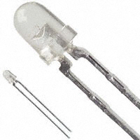
T-1 (3 mm) High Intensity LED Lamps
Description
The Broadcom® family of T-1 lamps is specially designed for
applications requiring higher on-axis intensity than is
achievable with a standard lamp. The light generated is
focused to a narrow beam to achieve this effect.
Features
High intensity
Choice of 3 bright colors
– Red
– Yellow
– Green
Popular T-1 diameter package
Narrow viewing angle
General purpose leads
Reliable and rugged
Available on tape and reel
For more information, refer to the Tape and Reel Option
Data Sheet.
Broadcom
AV02-1068EN
August 6, 2021
�HLMP-132x Series, HLMP-142x Series, HLMP-152x Series Data Sheet
T-1 (3 mm) High Intensity LED Lamps
Package Dimensions
Ø
3.17 (.125)
2.67 (.105)
3.43 (.135)
2.92 (.115)
4.70 (.185)
4.19 (.165)
1.14 (.045)
0.51 (.020)
6.35 (.250)
5.58 (.220)
0.65 (0.026) max.
Cathode
24.1(.95) min.
1.52 (.060)
1.02 (.040)
(0.022) 0.55 SQ. TYP.
(0.016) 0.40
2.79 (.110)
2.29 (.090)
NOTE:
1. All dimensions are in millimeters (in.).
2. An epoxy meniscus may extend about 1 mm (0.40 in.) down the leads.
3. For PCB hole recommendations, see Precautions.
Device Selection Guide
Luminous Intensity Iv (mcd) at 10 mA
Part Number
Package Description
Material/Color
Min.
Max.
Tinted, Non-diffused
AlInGaP Red
8.6
—
HLMP-1420
Microtinted, Non-diffused
AlInGaP Yellow
HLMP-1421
Tinted, Non-diffused
HLMP-1321
HLMP-1321-G00xx
HLMP-1421-F00xx
HLMP-1520
Microtinted, Non-diffused
HLMP-1521
Tinted, Non-diffused
HLMP-1521-E00xx
Broadcom
AlInGaP Green
8.6
—
9.2
—
9.2
—
9.2
—
6.7
—
6.7
—
6.7
—
AV02-1068EN
2
�HLMP-132x Series, HLMP-142x Series, HLMP-152x Series Data Sheet
T-1 (3 mm) High Intensity LED Lamps
Absolute Maximum Ratings at TA = 25°C
Parameter
Red
Yellow
Green
Units
Peak Forward Current
90
60
90
mA
Average Forward Currenta
25
20
25
mA
DC Currentb
30
20
30
mA
Power Dissipationc
135
85
135
mW
5
5
5
V
110
110
110
°C
°C
Reverse Voltage (IR = 100 µA)
LED Junction Temperature
Operating Temperature Range
–40 to +100
–40 to +100
–20 to +100
Storage Temperature Range
–40 to +100
–40 to +100
–40 to +100
a. See Figure 4 (Red), Figure 8 (Yellow), or Figure 12 (Green) to establish pulsed operating conditions.
b. For Red and Green series, derate linearly from 50°C at 0.5 mA/°C. For Yellow series, derate linearly from 50°C at 0.2 mA/°C.
c. For Red and Green series, derate power linearly from 25°C at 1.8 mW/°C. For Yellow series, derate power linearly from 50°C at 1.6 mW/°C.
Broadcom
AV02-1068EN
3
�HLMP-132x Series, HLMP-142x Series, HLMP-152x Series Data Sheet
T-1 (3 mm) High Intensity LED Lamps
Electrical/Optical Characteristics at TA = 25°C
Device
Symbol
Description
HLMP-
Min.
Typ.
Max.
Units
2½
Including Angle Between Half Luminous
Intensity Points
All
—
45
—
Deg.
132x
—
632
—
nm
142X
—
590
—
152X
—
570
—
132x
—
14
—
142X
—
12
—
PEAK
½
d
s
C
RJ-PIN
VF
Peak Wavelength
Spectral Line Halfwidth
Dominant Wavelength
Speed of Response
Capacitance
Thermal Resistance
Forward Voltage
VR
Reverse Breakdown Voltage
V
Luminous Efficacy
Test Conditions
IF = 10 mA, see Note a
Measurement
at Peak
nm
152X
—
13
—
132x
—
626
—
142X
—
589
—
152X
—
569
—
132x
—
90
—
142X
—
90
—
152X
—
500
—
132x
—
11
—
142X
—
15
—
152X
—
18
—
All
—
290
—
°C/W
132x
—
1.9
2.4
V
IF = 10 mA
142X
—
1.9
2.4
152X
—
2.0
2.7
All
5.0
—
—
V
IR = 100 µA
132x
—
180
—
lm/W
See Note c
142X
—
500
—
152X
—
640
—
nm
See Note b
ns
pF
VF = 0; f = 1 MHz
Junction to Cathode Lead
a. ½ is the off-axis angle at which the luminous intensity is half the axial luminous intensity.
b. The dominant wavelength, d, is derived from the CIE chromaticity diagram and represents the single wavelength which defines the color of
the device.
c. Radiant intensity, Ie, in watts/steradian, may be found from the equation Ie = lv/v, where lv is the luminous intensity in candelas and v is the
luminous efficacy in lumens/watt.
Broadcom
AV02-1068EN
4
�HLMP-132x Series, HLMP-142x Series, HLMP-152x Series Data Sheet
T-1 (3 mm) High Intensity LED Lamps
Part Numbering System
H
L
M
P
-
x1
x2
x3
x4
-
x5
x6
x7
x8
x9
Code
Description
x1
Package type
1
T-1 (3 mm)
x2
Color
3
Red
4
Yellow
5
Green
20
Untinted or Micro Tinted, Non-diffused
21
Tinted, Non-diffused
x3 x4
Lens Appearance
Option
x5
Minimum intensity bin
x6
Maximum intensity bin
x7
Color bin selection
0
Full range
x8 x9
Packaging option
00
Bulk packaging
01
Tape and Reel, Crimped Leads
Broadcom
See Intensity Bin Limits
02
Tape and Reel, Straight Leads
A1
Right Angle Housing, Uneven Leads
A2
Right Angle Housing, Even Leads
AV02-1068EN
5
�HLMP-132x Series, HLMP-142x Series, HLMP-152x Series Data Sheet
T-1 (3 mm) High Intensity LED Lamps
Intensity Bin Limits
Intensity Range (mcd)
Intensity Range (mcd)
Color
Bin
Min.
Max.
Color
Bin
Min.
Max.
Red
G
9.7
15.5
Green
E
7.6
12.0
H
15.5
24.8
F
12.0
19.1
I
24.8
39.6
G
19.1
30.7
J
39.6
63.4
H
30.7
49.1
Yellow
K
63.4
101.5
I
49.1
78.5
L
101.5
162.4
J
78.5
125.7
M
162.4
234.6
K
125.7
201.1
289.0
N
234.6
340.0
L
201.1
O
340.0
540.0
M
289.0
417.0
P
540.0
850.0
N
417.0
680.0
Q
850.0
1200.0
O
680.0
1100.0
R
1200.0
1700.0
P
1100.0
1800.0
S
1700.0
2400.0
Q
1800.0
2700.0
4300.0
T
2400.0
3400.0
R
2700.0
U
3400.0
4900.0
S
4300.0
6800.0
V
4900.0
7100.0
T
6800.0
10800.0
W
7100.0
10200.0
U
10800.0
16000.0
X
10200.0
14800.0
V
16000.0
25000.0
Y
14800.0
21400.0
W
25000.0
40000.0
Z
21400.0
30900.0
F
10.3
16.6
G
16.6
26.5
H
26.5
42.3
I
42.3
67.7
J
67.7
108.2
K
108.2
173.2
L
173.2
250.0
M
250.0
360.0
Maximum tolerance for each bin limit is ± 18%.
Color Categories
Lambda (nm)
Color
Category
Number
Min.
Max.
Green
6
561.5
564.5
N
360.0
510.0
5
564.5
567.5
O
510.0
800.0
4
567.5
570.5
P
800.0
1250.0
3
570.5
573.5
2
573.5
576.5
Q
1250.0
1800.0
R
1800.0
2900.0
1
582.0
584.5
S
2900.0
4700.0
3
584.5
587.0
Yellow
T
4700.0
7200.0
2
587.0
589.5
U
7200.0
11700.0
4
589.5
592.0
V
11700.0
18000.0
5
592.0
593.0
W
18000.0
27000.0
Tolerance for each bin limit is ± 0.5 nm.
Broadcom
AV02-1068EN
6
�HLMP-132x Series, HLMP-142x Series, HLMP-152x Series Data Sheet
T-1 (3 mm) High Intensity LED Lamps
Packaging Option Matrix
Packaging Option Code
NOTE:
Definition
00
Bulk Packaging, minimum increment 500 pieces/bag
01
Tape and Reel, crimped leads, minimum increment 1800 pieces/reel
02
Tape and Reel, straight leads, minimum increment 1800 pieces/reel
A1
Right Angle Housing, uneven leads, minimum increment 500 pieces/bag
A2
Right Angle Housing, even leads, minimum increment 500 pieces/bag
All categories are established for classification of products. Products may not be available in all categories. Contact
your local Broadcom representative for further clarification or information.
Figure 1: Relative Intensity vs. Wavelength
1
RELATIVE INTENSITY
0.9
YELLOW
GREEN
0.8
RED
0.7
0.6
0.5
0.4
0.3
0.2
0.1
0
500
550
600
650
700
WAVELENGTH - nm
Broadcom
AV02-1068EN
7
�HLMP-132x Series, HLMP-142x Series, HLMP-152x Series Data Sheet
T-1 (3 mm) High Intensity LED Lamps
T-1 Red Non-Diffused
Figure 2: Forward Current vs. Forward Voltage
Figure 3: Relative Luminous Intensity vs. DC Forward Current
2
30
RELATIVE LUMINOUS INTENSITY
(NORMALIZED AT 10 mA)
FORWARD CURRENT - mA
25
20
15
10
5
0
0
1
2
1.5
1
0.5
3
0
FORWARD VOLTAGE - V
0
5
10
15
20
25
30
DC FORWARD CURRENT - mA
6
5
4
3
2
Hz
Hz
1,000
100
300
z
z
100
1 KH
Hz
Hz
10
3 KH
10 K
Hz
1
1.0
30 K
KHz
100 K
300
IPEAK MAX.
IDC MAX.
RATIO OF MAXIMUM
TOLERABLE PEAK CURRENT
TO MAXIMUM TOLERABLE
DC CURRENT
Figure 4: Maximum Tolerable Peak Current vs. Pulse Duration
(IDC MAX as per MAX Ratings)
10,000
tp – PULSE DURATION – μs
Figure 5: Relative Luminous Intensity vs. Angular Displacement
20°
10°
0°
1.0
30°
.8
40°
50°
.6
60°
.4
70°
.2
80°
90°
Broadcom
NON-DIFFUSED
0°
20°
40°
60°
80°
100°
AV02-1068EN
8
�HLMP-132x Series, HLMP-142x Series, HLMP-152x Series Data Sheet
T-1 (3 mm) High Intensity LED Lamps
T-1 Yellow Non-Diffused
Figure 6: Forward Current vs. Forward Voltage
Figure 7: Relative Luminous Intensity vs. DC Forward Current
2
30
RELATIVE LUMINOUS INTENSITY
(NORMALIZED AT 10 mA)
FORWARD CURRENT - mA
25
20
15
10
5
0
0
1
2
1.5
1
0.5
3
0
FORWARD VOLTAGE - V
0
5
10
15
20
DC FORWARD CURRENT - mA
6
5
4
3
Hz
Hz
1,000
100
300
z
z
100
1 KH
Hz
Hz
Hz
10
3 KH
10 K
30 K
KHz
1
1.0
100 K
IDC MAX.
2
300
IPEAK MAX.
RATIO OF MAXIMUM
TOLERABLE PEAK CURRNT
TO MAXIMUM TOLERABLE
DC CURRENT
Figure 8: Maximum Tolerable Peak Current vs. Pulse Duration
(IDCMAX as per MAX Ratings)
10,000
tp – PULSE DURATION – μs
Figure 9: Relative Luminous Intensity vs. Angular Displacement
20°
10°
0°
1.0
30°
.8
40°
50°
.6
60°
.4
70°
.2
80°
90°
Broadcom
NON-DIFFUSED
0°
20°
40°
60°
80°
100°
AV02-1068EN
9
�HLMP-132x Series, HLMP-142x Series, HLMP-152x Series Data Sheet
T-1 (3 mm) High Intensity LED Lamps
T-1 Green Non-Diffused
Figure 10: Forward Current vs. Forward Voltage
Figure 11: Relative Luminous Intensity vs. DC Forward Current
30
2.5
RELATIVE LUMINOUS INTENSITY
(NORMALIZED AT 10 mA)
FORWARD CURRENT - mA
25
20
15
10
5
0
0
1
2
3
2
1.5
1
0.5
0
FORWARD VOLTAGE - V
0
5
10
15
20
25
DC FORWARD CURRENT - mA
30
6
5
4
3
100
300
Hz
z
Hz
z
100
1 KH
3 KH
Hz
Hz
10
Hz
10 K
30 K
KHz
1
1.0
100 K
IDC MAX.
2
300
IPEAK MAX.
RATIO OF MAXIMUM
TOLERABLE PEAK CURRNT
TO MAXIMUM TOLERABLE
DC CURRENT
Figure 12: Maximum Tolerable Peak Current vs. Pulse
Duration (IDCMAX as per MAX Ratings)
1,000
10,000
tp – PULSE DURATION – μs
Figure 13: Relative Luminous Intensity vs. Angular Displacement
20°
10°
0°
1.0
30°
.8
40°
50°
.6
60°
.4
70°
.2
80°
90°
Broadcom
NON-DIFFUSED
0°
20°
40°
60°
80°
100°
AV02-1068EN
10
�HLMP-132x Series, HLMP-142x Series, HLMP-152x Series Data Sheet
Precautions
T-1 (3 mm) High Intensity LED Lamps
Lead Forming
The leads of an LED lamp may be preformed or cut to
length prior to insertion and soldering on PC board.
For better control, use the proper tool to precisely form
and cut the leads to applicable length rather than doing
it manually.
If manual lead cutting is necessary, cut the leads after
the soldering process. The solder connection forms a
mechanical ground that prevents mechanical stress
due to lead cutting from traveling into LED package.
Use this method for the hand soldering operation,
because the excess lead length also acts as small heat
sink.
Soldering and Handling
Take care during the PCB assembly and soldering
process to prevent damage to the LED component.
LED component may be effectively hand soldered to
PCB. However, do this under unavoidable
circumstances, such as rework. The closest manual
soldering distance of the soldering heat source
(soldering iron’s tip) to the body is 1.59 mm. Soldering
the LED using soldering iron tip closer than 1.59 mm
might damage the LED.
Apply ESD precautions on the soldering station and
personnel to prevent ESD damage to the LED
component that is ESD sensitive. Refer to Broadcom
application note AN 1142 for details. The soldering iron
used must have a grounded tip to ensure electrostatic
charge is properly grounded.
Recommended soldering condition.
Wave Solderinga, b
NOTE:
1. PCBs with different size and design (component
density) will have a different heat mass (heat capacity).
This might cause a change in temperature experienced
by the board if the same wave soldering setting is used.
Therefore, re-calibrate the soldering profile again before
loading a new type of PCB.
2. Take extra precautions during wave soldering to ensure
that the maximum wave temperature does not exceed
250°C and the solder contact time does not exceed 3s.
Over-stressing the LED during the soldering process
might cause premature failure to the LED due to
delamination.
1.59 mm
Manual Solder Dipping
Pre-heat Temperature
105°C max.
—
Pre-heat Time
60s max.
—
Peak Temperature
250°C max.
260°C max.
Dwell Time
3s max.
5s max.
Set and maintain wave soldering parameters according
to the recommended temperature and dwell time.
Perform daily checks on the soldering profile to ensure
that it always conforms to the recommended soldering
conditions.
Loosely fit any alignment fixture that is being applied
during wave soldering and do not apply weight or force
on the LED. Use non-metal material because it will
absorb less heat during the wave soldering process.
At elevated temperature, LED is more susceptible to
mechanical stress. Therefore, allow the PCB to cool
down to room temperature prior to handling, which
includes removal of alignment fixture or pallet.
If PCB board contains both through-hole (TH) LED and
other surface-mount components, solder surface-mount
components on the top side of the PCB. If the surface
mount must be on the bottom side, solder these
components using reflow soldering prior to the insertion
of the TH LED.
The recommended PC board plated through holes
(PTH) size for LED component leads follows.
LED
Component
Lead Size
Diagonal
Plated ThroughHole Diameter
Lead size (typ.) 0.45 × 0.45 mm 0.636 mm 0.98 to 1.08 mm
(0.018 × 0.018 in.) (0.025 in.) (0.039 to 0.043 in.)
Dambar shear- 0.65 mm
off area (max.) (0.026 in.)
0.919 mm
(0.036 in.)
Lead size (typ.) 0.50 × 0.50 mm 0.707 mm 1.05 to 1.15 mm
(0.020 × 0.020 in.) (0.028 in.) (0.041 to 0.045 in.)
Dambar shear- 0.70 mm
off area (max.) (0.028 in.)
0.99 mm
(0.039 in.)
a. The preceding conditions refer to measurement with a
thermocouple mounted at the bottom of the PCB.
b. Use only bottom pre-heaters to reduce thermal stress
experienced by LED.
Broadcom
NOTE:
Refer to application note AN1027 for more
information on soldering LED components.
AV02-1068EN
11
�HLMP-132x Series, HLMP-142x Series, HLMP-152x Series Data Sheet
T-1 (3 mm) High Intensity LED Lamps
Over-sizing the PTH can lead to twisted LED after clinching. On the other hand, under-sizing the PTH can cause
difficulty inserting the TH LED.
Refer to application note AN5334 for more information about soldering and handling of TH LED lamps.
Figure 14: Example of Wave Soldering Temperature Profile for TH LED
Recommended solder:
Sn63 (Leaded solder alloy)
SAC305 (Lead-free solder alloy)
LAMINAR
HOT AIR KNIFE
TURBULENT WAVE
250
Flux: Rosin flux
Solder bath temperature:
245qC ± 5 qC (maximum peak temperature = 250qC)
TEMPERATURE (qC)
200
Dwell time: 1.5s – 3.0s (maximum = 3 seconds)
150
Note: Allow for board to be sufficiently cooled to
room temperature before you exert mechanical force.
100
50
PREHEAT
0
Broadcom
10
20
30
40
50
60
TIME (SECONDS)
70
80
90
100
AV02-1068EN
12
�Broadcom, the pulse logo, Connecting everything, Avago Technologies, Avago, and the A logo are among the trademarks
of Broadcom and/or its affiliates in the United States, certain other countries, and/or the EU.
Copyright © 2013–2021 Broadcom. All Rights Reserved.
The term “Broadcom” refers to Broadcom Inc. and/or its subsidiaries. For more information, please visit www.broadcom.com.
Broadcom reserves the right to make changes without further notice to any products or data herein to improve reliability,
function, or design. Information furnished by Broadcom is believed to be accurate and reliable. However, Broadcom does
not assume any liability arising out of the application or use of this information, nor the application or use of any product or
circuit described herein, neither does it convey any license under its patent rights nor the rights of others.
�