HLMP-1301, HLMP-1401, HLMP-1503,
HLMP-K401, HLMP-K600
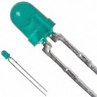
T-1 (3-mm) Diffused LED Lamps
Data Sheet
Description
Features
This family of T-1 lamps is widely used in general-purpose
indicator applications. Diffusants, tints, and optical design are
balanced to yield superior light output and wide viewing
angles. Several intensity choices are available in each color for
increased design flexibility.
High intensity
Choice of four bright colors:
— High Efficiency Red
— Orange
— Yellow
— High Performance Green
Popular T-1 diameter package
Selected minimum intensities
Wide viewing angle
General purpose leads
Reliable and rugged
Available on tape and reel
Package Dimensions
1.14 (.045)
0.51 (.020)
3.43 (.135)
2.92 (.115)
2.79 (.110)
2.29 (.090)
24.1(.95) MIN.
CATHODE
0.65 (0.026) max.
1.52 (.060)
1.02 (.040)
3.17 (.125)
2.67 (.105)
(0.022) 0.55 SQ. TYP.
(0.016) 0.40
4.70 (.185)
4.19 (.165)
6.35 (.250)
5.58 (.220)
NOTE
1.
2.
3.
All dimensions are in mm (inches).
An epoxy meniscus may extend about 1 mm (0.040 in.) down the leads.
For PCB hole recommendations, see Precautions.
Broadcom
-1-
�HLMP-1301, HLMP-1401, HLMP-1503, HLMP-K401, HLMP-K600
Data Sheet
Device Selection Guide
Luminous Intensity Iv (mcd) at 10 mA
Material
Color
Part Number
Min.
GaAsP on GaP
Red
Yellow
Orange
GaP
Green
Emerald Green
a.
a
Max.
HLMP-1301
3.4
—
HLMP-1301-E00xx
3.4
—
HLMP-1301-G00xx
8.6
—
HLMP-1301-GH0xx
8.6
27.6
HLMP-1401
2.2
—
HLMP-1401-D00xx
3.6
—
HLMP-1401-E0000
5.7
—
HLMP-K401
2.1
—
HLMP-K401-E00xx
3.4
—
HLMP-K401-FGDxx
5.4
17.2
HLMP-K401-FH000
5.4
27.6
HLMP-1503
1.0
—
HLMP-1503-C00xx
2.6
—
HLMP-1503-D00xx
4.2
—
HLMP-1503-DE000
4.2
13.4
HLMP-1503-E00xx
6.7
—
HLMP-K600
1.0
—
Refer to Application Note 1061 for information comparing standard green and emerald green light output degradation.
Absolute Maximum Ratings at TA = 25°C
Parameter
HER/Orange
Yellow
Green
Units
Peak Forward Current
90
60
90
mA
Average Forward Currenta
25
20
25
mA
DC Currentb, c
30
20
30
mA
Reverse Voltage (IR = 100 A)
5
5
5
V
Transient Forward Currentd (10s Pulse)
500
500
500
mA
LED Junction Temperature
110
110
110
°C
Operating Temperature Range
–40 to +100
–40 to +100
–20 to +100
°C
Storage Temperature Range
–40 to +100
–40 to +100
–40 to +100
°C
a.
See Figure 5 (HER/Orange), Figure 10 (Yellow), or Figure 15 (Green/Emerald Green) to establish pulsed operating conditions.
b.
For Red, Orange, and Green series derate linearly from 50°C at 0.5 mA/°C. For Yellow series derate linearly from 50°C at 0.2 mA/°C.
c.
For Red, Orange, and Green series derate power linearly from 25°C at 1.8 mW/°C. For Yellow series derate power linearly from 50°C at 1.6 mW/°C.
d.
The transient peak current is the maximum non-recurring peak current that can be applied to the device without damaging the LED die and wirebond. It is
not recommended that the device be operated at peak currents beyond the peak forward current listed in the Absolute Maximum Ratings.
Broadcom
-2-
�HLMP-1301, HLMP-1401, HLMP-1503, HLMP-K401, HLMP-K600
Data Sheet
Electrical/Optical Characteristics at TA = 25°C
Parameter
Symbol
Device
Included Angle Between Half
Luminous Intensity Points
21/2
Peak Wavelength
PEAK
Dominant Wavelength
Spectral Line Halfwidth
Speed of Response
Capacitance
d
1/2
s
C
Min.
Typ.
Max.
Units
Test Conditions
All
—
60
—
Deg.
IF = 10 mA, See Note a
High Efficiency Red
—
635
—
nm
Measurement at Peak
Orange
—
600
—
Yellow
—
583
—
Green
—
565
—
nm
See Note b
Emerald Green
—
558
—
High Efficiency Red
—
626
—
Orange
—
602
—
Yellow
—
585
—
Green
—
569
—
Emerald Green
—
560
—
High Efficiency Red
—
40
—
Yellow
—
36
—
Green
—
28
—
Emerald Green
—
24
—
High Efficiency Red
—
90
—
Orange
—
280
—
Yellow
—
90
—
Green
—
500
—
Emerald Green
—
3100
—
High Efficiency Red
—
11
—
Orange
—
4
—
Yellow
—
15
—
Green
—
18
—
Emerald Green
—
35
—
nm
ns
pF
VF = 0; f = 1 MHz
Thermal Resistance
RJ-PIN
All
—
290
—
°C/W
Forward Voltage
VF
HER/Orange
1.5
1.9
2.4
V
IF = 10 mA
V
IR = 100 μA
Yellow
1.5
2.0
2.4
Green
1.5
2.1
2.7
Emerald Green
—
2.1
2.7
Reverse Breakdown Voltage
VR
All
5.0
—
—
Luminous Efficacy
V
High Efficiency Red
—
145
—
Orange
—
380
—
Yellow
—
500
—
Green
—
595
—
Emerald Green
—
655
—
Junction to Cathode Lead
lumens/ See Note c
watt
a.
1/2 is the off-axis angle at which the luminous intensity is half the axial luminous intensity.
b.
The dominant wavelength,d, is derived from the CIE chromaticity diagram and represents the single wavelength which defines the color of the device.
c.
Radiant intensity, le, in watts/steradian, may be found from the equation Ie = Iv/v, where Iv is the luminous intensity in candelas and v is the luminous
efficacy in lumens/watt.
Broadcom
-3-
�HLMP-1301, HLMP-1401, HLMP-1503, HLMP-K401, HLMP-K600
Data Sheet
Part Numbering System
H
L
M
P
-
x1
x2
x3
x4
-
x5
x6
x7
x8
x9
Code
Description
Option
x1
Package type
1
T-1 (3 mm)
K
T-1 (3 mm)
x2
Color
3
GaP HER
4
GaP Yellow (except K4xx series)
5
GaP Green
6
GaP Emerald Green
x3 x4
Product specific designation
—
x5
Minimum intensity bin
Refer to Intensity Bin Limits Table
x6
Maximum intensity bin
x7
Color bin selection
x8 x9
Packaging option
0
Full range
D
Color Bin 4 and 5 only
00
Bulk packaging
02
Tape and Reel, Straight Leads
A1
Right Angle Housing, Uneven Leads
A2
Right Angle Housing, Even Leads
FG
Products need inventory control for customer IDI
Broadcom
-4-
�HLMP-1301, HLMP-1401, HLMP-1503, HLMP-K401, HLMP-K600
Data Sheet
Intensity Bin Limts
Table 1 Intensity Bin Limits (Continued)
Intensity Range (mcd)
Color
Bin
Min.
Max.
C
2.5
4.0
D
4.0
6.5
E
6.5
10.3
Table 1 Intensity Bin Limits
Intensity Range (mcd)
Color
Red/Orange
Bin
Min.
Max.
D
2.4
3.8
E
3.8
6.1
F
6.1
9.7
G
9.7
15.5
H
15.5
24.8
I
24.8
39.6
J
39.6
63.4
K
63.4
101.5
L
101.5
162.4
M
162.4
234.6
N
234.6
340.0
O
340.0
540.0
P
540.0
850.0
Q
850.0
1200.0
R
1200.0
1700.0
S
1700.0
2400.0
T
2400.0
3400.0
U
3400.0
4900.0
V
4900.0
7100.0
W
7100.0
10200.0
X
10200.0
14800.0
Y
14800.0
21400.0
Z
21400.0
30900.0
Yellow
Broadcom
-5-
F
10.3
16.6
G
16.6
26.5
H
26.5
42.3
I
42.3
67.7
J
67.7
108.2
K
108.2
173.2
L
173.2
250.0
M
250.0
360.0
N
360.0
510.0
O
510.0
800.0
P
800.0
1250.0
Q
1250.0
1800.0
R
1800.0
2900.0
S
2900.0
4700.0
T
4700.0
7200.0
U
7200.0
11700.0
V
11700.0
18000.0
W
18000.0
27000.0
�HLMP-1301, HLMP-1401, HLMP-1503, HLMP-K401, HLMP-K600
Data Sheet
Color Categories
Table 1 Intensity Bin Limits (Continued)
Intensity Range (mcd)
Color
Bin
Green/Emerald
Green
NOTE
NOTE
Min.
Max.
A
1.1
1.8
B
1.8
2.9
C
2.9
4.7
D
4.7
7.6
E
7.6
12.0
F
12.0
19.1
G
19.1
30.7
H
30.7
49.1
I
49.1
78.5
J
78.5
125.7
K
125.7
201.1
L
201.1
289.0
M
289.0
417.0
N
417.0
680.0
O
680.0
1100.0
P
1100.0
1800.0
Q
1800.0
2700.0
R
2700.0
4300.0
S
4300.0
6800.0
T
6800.0
10800.0
U
10800.0
16000.0
V
16000.0
25000.0
W
25000.0
40000.0
Maximum tolerance for each bin limit is
± 18%.
All categories are established for classification
of products. Products may not be available in
all categories. Contact your local Broadcom
representative for further clarification or
information.
Lambda (nm)
C olor
Category #
Emerald Green
Green
Yellow
Orange
NOTE
Min.
Max.
9
522.5
555.5
8
555.5
558.5
7
558.5
561.5
6
561.5
564.5
6
561.5
564.5
5
564.5
567.5
4
567.5
570.5
3
570.5
573.5
2
573.5
576.5
1
582.0
584.5
3
584.5
587.0
2
587.0
589.5
4
589.5
592.0
5
592.0
593.0
1
597.0
599.5
2
599.5
602.0
3
602.0
604.5
4
604.5
607.5
5
607.5
610.5
6
610.5
613.5
7
613.5
616.5
8
616.5
619.5
Tolerance for each bin limit is ± 0.5 nm.
Packaging Option Matrix
Packaging
Option Code
Broadcom
-6-
Definition
00
Bulk Packaging, minimum increment,
500 pcs/bag
02
Tape & Reel, straight leads, minimum increment,
1800 pcs/bag
A1
Right Angle Housing, uneven leads, minimum
increment, 500 pcs/bag
A2
Right Angle Housing, even leads, minimum
increment, 500 pcs/bag
FG
Inventory Control for Customer IDI
�HLMP-1301, HLMP-1401, HLMP-1503, HLMP-K401, HLMP-K600
Data Sheet
Figure 1 Relative Intensity vs. Wavelength
RELATIVE INTENSITY
1.0
EMERALD GREEN
ORANGE
HIGH
PERFORMANCE
GREEN
AlGaAs RED
T A = 25° C
HIGH EFFICIENCY RED
0.5
YELLOW
0
500
550
600
650
WAVELENGTH – nm
700
Broadcom
-7-
750
�HLMP-1301, HLMP-1401, HLMP-1503, HLMP-K401, HLMP-K600
Data Sheet
T-1 High Efficiency Red, Orange Diffused Lamps
Figure 2 Forward Current vs. Forward Voltage Characteristics
Figure 3 Relative Luminous Intensity vs. DC Forward Current
Figure 4 Relative Efficiency (Luminous Intensity per Unit Current)
vs. Peak LED Current
Figure 5 Maximum Tolerable Peak Current vs. Pulse Duration (IDC
MAX as per MAX Ratings)
Figure 6 Relative Luminous Intensity vs. Angular Displacement
Broadcom
-8-
�HLMP-1301, HLMP-1401, HLMP-1503, HLMP-K401, HLMP-K600
Data Sheet
T-1 Yellow Diffused Lamps
Figure 7 Forward Current vs. Forward Voltage Characteristics
Figure 8 Relative Luminous Intensity vs. Forward Current
Figure 9 Relative Efficiency (Luminous Intensity per Unit Current)
vs. Peak Current
Figure 10 Maximum Tolerable Peak Current vs. Pulse Duration (IDC
MAX as per MAX Ratings)
Figure 11 Relative Luminous Intensity vs. Angular Displacement
Broadcom
-9-
�HLMP-1301, HLMP-1401, HLMP-1503, HLMP-K401, HLMP-K600
Data Sheet
T-1 Green/Emerald Green Diffused Lamps
Figure 12 Forward Current vs. Forward Voltage Characteristics
Figure 13 Relative Luminous Intensity vs. Forward Current
Figure 14 Relative Efficiency (Luminous Intensity per Unit
Current) vs. Peak LED Current
Figure 15 Maximum Tolerable Peak Current vs. Pulse Duration (IDC
MAX as per MAX Ratings)
Figure 16 Relative Luminous Intensity vs. Angular Displacement
Broadcom
- 10 -
�HLMP-1301, HLMP-1401, HLMP-1503, HLMP-K401, HLMP-K600
Data Sheet
Precautions
Lead Forming
Preform or cut the leads of an LED lamp to length before
they are inserted and soldered into the PC board.
If forming a lead is required before it is soldered, take care
to avoid any excessive mechanical stress induced to the
LED package. Otherwise, cut the LED leads to length after
soldering at room temperature. The solder joint formed
will absorb the mechanical stress of the lead cutting from
traveling to the LED chip die attach and wirebond.
Make tooling precisely and cut the leads cut to length,
rather than relying on your hand.
Soldering Conditions
Take care during PCB assembly and soldering process to
prevent damage to LED component.
The closest an LED is allowed to be soldered on board is
1.59 mm below the body (encapsulant epoxy) for those
parts without standoff.
Follow the recommended soldering conditions in this
table.
LED Component
Lead Size
Wave Soldering
Manual Solder
Dipping
105°C Max.
—
30s Max.
—
250°C Max.
260°C Max.
3s Max.
5s Max.
Pre-heat Temperature
Pre-heat Time
Peak Temperature
Dwell Time
Set and maintain the wave soldering parameter according
to the recommended temperature and dwell time in the
solder wave. You are advised to periodically check the
soldering profile to ensure the soldering profile used
always conforms to recommended soldering condition.
If necessary, use a fixture during soldering process to hold
the LED component in the proper orientation with respect
to the PCB.
Handle the LED properly to avoid excessive thermal
stresses to LED components when heated. Therefore, the
soldered PCB must be allowed to cool to room
temperature, 25°C, before handling.
To ensure solderability, pay special attention to board
fabrication, solder masking, surface plating, and lead hole
size and component orientation.
Follow the recommended PC board plated through-hole
sizes for LED component leads in this table.
0.45 × 0.45 mm
(0.018 × 0.018 in.)
Dambar
shear-off area
(max.)
0.65 mm (0.026 in.) 0.919 mm
(0.036 in)
Lead size (typ.)
0.50 × 0.50 mm
(0.020 × 0.020 in.)
Dambar
shear-off area
(max.)
0.70 mm (0.028 in.) 0.99 mm
(0.039 in)
NOTE
LAMINAR WAVE
HOT AIR KNIFE
TURBULENT WAVE
TEMPERATURE – C
CONVEYOR SPEED = 1.83 M/MIN (6 FT/MIN)
PREHEAT SETTING = 150C (100C PCB)
SOLDER WAVE TEMPERATURE = 245C
AIR KNIFE AIR TEMPERATURE = 390C
AIR KNIFE DISTANCE = 1.91 mm (0.25 IN.)
AIR KNIFE ANGLE = 40
SOLDER: SN63; FLUX: RMA
150
FLUXING
100
50
30
PREHEAT
0
10
20
30
40
50
60
TIME – SECONDS
70
80
90
100
NOTE: ALLOW FOR BOARDS TO BE
SUFFICIENTLY COOLED BEFORE EXERTING
MECHANICAL FORCE.
Broadcom
- 11 -
0.707 mm 1.05 to 1.15 mm
(0.028 in) (0.041 to 0.045 in.)
Refer to application note AN1027 for more
information on soldering LED components.
BOTTOM SIDE
OF PC BOARD
TOP SIDE OF
PC BOARD
200
Plated
Through-Hole
Diameter
0.636 mm 0.98 to 1.08 mm
(0.025 in) (0.039 to 0.043 in.)
Lead size (typ.)
Figure 17 Recommended Wave Soldering Profile
250
Diagonal
�For product information and a complete list of distributors, please go to our web
site: www.broadcom.com.
Broadcom, the pulse logo, Connecting everything, Avago Technologies, Avago,
and the A logo are among the trademarks of Broadcom and/or its affiliates in the
United States, certain other countries and/or the EU.
Copyright © 2013–2017 by Broadcom. All Rights Reserved.
The term "Broadcom" refers to Broadcom Limited and/or its subsidiaries. For
more information, please visit www.broadcom.com.
Broadcom reserves the right to make changes without further notice to any
products or data herein to improve reliability, function, or design.
Information furnished by Broadcom is believed to be accurate and reliable.
However, Broadcom does not assume any liability arising out of the application
or use of this information, nor the application or use of any product or circuit
described herein, neither does it convey any license under its patent rights nor
the rights of others.
AV02-1555EN – July 14, 2017
�