Data Sheet
HLMP-1600, HLMP-1601, HLMP-1620, HLMP-1621,
HLMP-1640, HLMP-1641, HLMP-3600, HLMP-3601,
HLMP-3650, HLMP-3651, HLMP-3680, HLMP-3681
T-1¾ (5-mm), T-1 (3-mm), 5V, 12V, Integrated Resistor
LED Lamps
Overview
The Broadcom® 5V and 12V series lamps contain an
integral current limiting resistor in series with the LED. This
allows the lamp to be driven from a 5V/12V source without
an external current limiter.
Features
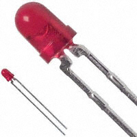
The diffused lamps provide a wide off-axis viewing angle.
The T-1¾ lamps are provided with sturdy leads suitable for
wire wrap applications. The T-1¾ lamps may be front panel
mounted by using the HLMP-0103 clip and ring.
Broadcom
Integral current limiting resistor
TTL compatible
– Requires no external current limiter with 5V/12V
supply
Cost effective
– Saves space and resistor cost
Wide viewing angle
Available in all colors
– Red, Yellow, and Green in T-1 and T-1¾ packages
AlInGaP LED technology
AV02-0379EN
March 22, 2022
�HLMP-1600, HLMP-1601, HLMP-1620, HLMP-1621,
HLMP-1640, HLMP-1641, HLMP-3600, HLMP-3601,
HLMP-3650, HLMP-3651, HLMP-3680, HLMP-3681 Data Sheet
T-1¾ (5-mm), T-1 (3-mm), 5V, 12V, Integrated Resistor
LED Lamps
Package Dimensions
Figure 1: T-1 Package
1.14 (.045)
0.51 (.020)
3.43 (.135)
2.92 (.115)
Ø
2.79 (.110)
2.29 (.090)
24.1(.95) MIN.
0.65 (0.026) max.
1.52 (.060)
1.02 (.040)
3.17 (.125)
2.67 (.105)
(0.022) 0.55 SQ. TYP.
(0.016) 0.40
4.70 (.185)
4.19 (.165)
6.35 (.250)
5.58 (.220)
Figure 2: T-1¾ Package
5.08 (0.200)
4.57 (0.180)
12.34 (0.486)
11.54 (0.454)
0.89 (0.035)
0.64 (0.025)
9.19 (0.362)
8.43 (0.332)
1.32 (0.052)
1.02 (0.040)
23.0
MIN.
(0.90)
0.46 (0.018)
SQUARE NOMINAL
1.27 (0.050)
NOM.
6.1 (0.240)
5.6 (0.220)
CATHODE
2.54 (0.100)
NOM.
NOTE:
1. All dimensions are in millimeters (inches).
2. An epoxy meniscus can extend about 1 mm (0.040 in.) down the leads.
3. For PCB hole recommendations, see the Precautions section.
Broadcom
AV02-0379EN
2
�HLMP-1600, HLMP-1601, HLMP-1620, HLMP-1621,
HLMP-1640, HLMP-1641, HLMP-3600, HLMP-3601,
HLMP-3650, HLMP-3651, HLMP-3680, HLMP-3681 Data Sheet
T-1¾ (5-mm), T-1 (3-mm), 5V, 12V, Integrated Resistor
LED Lamps
Device Selection Guide
Color
Red
Package Description
Package
Outline
T-1 Tinted Diffused
Figure 1
T-1¾ Tinted Diffused
Yellow
T-1 Tinted Diffused
T-1¾ Tinted Diffused
Green
T-1 Tinted Diffused
T-1¾ Tinted Diffused
2θ1/2a
Operating
Voltage (V)
Part Number
HLMP-
60
5
60
12
60
5
Figure 2
Figure 1
Figure 2
Figure 1
Figure 2
Luminous Intensity IV (mcd)
Min.
Max.
1600
2.1
—
1600-D00xx
2.1
—
1601
2.1
—
3600
2.1
—
3600-D00xx
2.1
—
60
12
3601
2.1
—
60
5
1620
2.2
—
1620-C00xx
2.2
—
60
12
1621
2.2
—
60
5
3650
2.2
—
3650-C00xx
2.2
—
60
12
3651
2.2
—
60
5
1640
1.6
—
1640-B00xx
1.6
—
1640-FH0xx
10.6
54.6
60
12
1641
1.6
—
60
5
3680
1.6
—
3680-B00xx
1.6
—
60
12
3681
1.6
—
3681-B00xx
1.6
—
a. θ1/2 is the off-axis angle at which the luminous intensity is 1/2 the axial luminous intensity.
Absolute Maximum Ratings
Parameter
DC Forward Voltage (TA = 25°C)
Red/Yellow
5V Lamps
Red/Yellow
12V Lamps
Green
5V Lamps
Green
12V Lamps
7.5Va
15Vb
7.5Va
15Vb
5V
5V
5V
5V
Reverse Voltage (IR = 100 μA)
Operating Temperature Range
–40°C to +85°C
–20°C to +85°C
Storage Temperature Range
–40°C to +100°C
–40°C to +100°C
a. Derate from TA = 50°C at 0.071 V/°C; see Figure 6.
b. Derate from TA = 50°C at 0.086 V/°C; see Figure 7.
Broadcom
AV02-0379EN
3
�HLMP-1600, HLMP-1601, HLMP-1620, HLMP-1621,
HLMP-1640, HLMP-1641, HLMP-3600, HLMP-3601,
HLMP-3650, HLMP-3651, HLMP-3680, HLMP-3681 Data Sheet
T-1¾ (5-mm), T-1 (3-mm), 5V, 12V, Integrated Resistor
LED Lamps
Optical and Electrical Characteristics at TA = 25°C
Parameter
Symbol
Color
Min.
Typ.
Max.
Units
PEAK
Red
Yellow
Green
—
—
—
632
590
570
—
—
—
nm
Dominant Wavelengtha
d
Red
Yellow
Green
—
—
—
626
589
569
—
—
—
nm
Spectrum Line Halfwidth
1/2
Red
Yellow
Green
—
—
—
14
12
13
—
—
—
nm
Thermal Resistanceb
RθJ-PIN
Red
Yellow
Green
—
—
—
290
290
290
—
—
—
°C/W
Junction to Cathode Lead
Thermal Resistancec
RθJ-PIN
Red
Yellow
Green
—
—
—
210
210
210
—
—
—
°C/W
Junction to Cathode Lead
Forward Current,
12V Devices
IF
Red
Yellow
Green
—
—
—
13
13
13
20
20
20
mA
VF = 12V
Forward Current,
5V Devices
IF
Red
Yellow
Green
—
—
—
10
10
10
15
15
15
mA
VF = 5V
Luminous Efficacyd
V
Red
Yellow
Green
—
—
—
180
500
640
—
—
—
Lumen/
Watt
Reverse Breakdown
Voltage
VR
Red
Yellow
Green
5
5
5
—
—
—
—
—
—
V
Peak Wavelength
Test Conditions
IR = 100 µA
a. The dominant wavelength, d, is derived from the Chromaticity diagram and represents the color of the lamp.
b. For Figure 1, T-1 Package, package type.
c.
For Figure 2, T-1¾ Package, package type.
d. Radiant intensity, le, in watts/steradian, can be found from the equation Ie = Iv / v, where Iv is the luminous intensity in candelas and v is the
luminous efficacy in lumens/watt.
Broadcom
AV02-0379EN
4
�HLMP-1600, HLMP-1601, HLMP-1620, HLMP-1621,
HLMP-1640, HLMP-1641, HLMP-3600, HLMP-3601,
HLMP-3650, HLMP-3651, HLMP-3680, HLMP-3681 Data Sheet
T-1¾ (5-mm), T-1 (3-mm), 5V, 12V, Integrated Resistor
LED Lamps
Part Numbering System
H
L
M
P
-
x1
6
x2
x3
-
x4
x5
x6
x7
x8
Code
Description
Option
x1
Package Type
1
3
T-1¾ (5 mm)
x2
Color
0
Red
2, 5
Yellow
4, 8
Green
0
5V
1
12V
x3
Operating Voltage
T-1 (3 mm)
x4
Minimum Intensity Bin
See the Intensity Bin Limits table.
x5
Maximum Intensity Bin
0
Open bins (no maximum IV bin limit)
x6
Color Bin Option
0
Full distribution
x7 x8
Packaging Option
00
Bulk (loose forms packaging)
A1, B1
Right angle housing, uneven leads
A2, B2
Right angle housing, even leads
Broadcom
AV02-0379EN
5
�HLMP-1600, HLMP-1601, HLMP-1620, HLMP-1621,
HLMP-1640, HLMP-1641, HLMP-3600, HLMP-3601,
HLMP-3650, HLMP-3651, HLMP-3680, HLMP-3681 Data Sheet
T-1¾ (5-mm), T-1 (3-mm), 5V, 12V, Integrated Resistor
LED Lamps
Bin Information
Intensity Bin Limits
Intensity Range (mcd)
Intensity Range (mcd)
Color
Red
Yellow
Broadcom
Bin
Min.
Max.
D
E
F
G
H
I
J
K
L
M
N
O
P
Q
R
S
T
U
V
W
X
Y
Z
C
D
E
F
G
H
I
J
K
L
M
N
O
P
Q
R
S
T
U
V
2.4
3.8
6.1
9.7
15.5
24.8
39.6
63.4
101.5
162.4
234.6
340.0
540.0
850.0
1200.0
1700.0
2400.0
3400.0
4900.0
7100.0
10200.0
14800.0
21400.0
2.5
4.0
6.5
10.3
16.6
26.5
42.3
67.7
108.2
173.2
250.0
360.0
510.0
800.0
1250.0
1800.0
2900.0
4700.0
7200.0
11700.0
3.8
6.1
9.7
15.5
24.8
39.6
63.4
101.5
162.4
234.6
340.0
540.0
850.0
1200.0
1700.0
2400.0
3400.0
4900.0
7100.0
10200.0
14800.0
21400.0
30900.0
4.0
6.5
10.3
16.6
26.5
42.3
67.7
108.2
173.2
250.0
360.0
510.0
800.0
1250.0
1800.0
2900.0
4700.0
7200.0
11700.0
18000.0
Color
Yellow (cont.)
Green
Bin
Min.
Max.
W
B
C
D
E
F
G
H
I
J
K
L
M
N
O
P
Q
R
S
T
U
V
W
18000.0
1.8
2.9
4.7
7.6
12.0
19.1
30.7
49.1
78.5
125.7
201.1
289.0
417.0
680.0
1100.0
1800.0
2700.0
4300.0
6800.0
10800.0
16000.0
25000.0
27000.0
2.9
4.7
7.6
12.0
19.1
30.7
49.1
78.5
125.7
201.1
289.0
417.0
680.0
1100.0
1800.0
2700.0
4300.0
6800.0
10800.0
16000.0
25000.0
40000.0
Maximum tolerance for each bin limit is ±18%.
Color Categories
Lambda (nm)
Color
Category #
Min.
Max.
Green
6
5
4
3
2
1
3
2
4
5
561.5
564.5
567.5
570.5
573.5
582.0
584.5
587.0
589.5
592.0
564.5
567.5
570.5
573.5
576.5
584.5
587.0
589.5
592.0
593.0
Yellow
Tolerance for each bin limit is ± 0.5 nm.
AV02-0379EN
6
�HLMP-1600, HLMP-1601, HLMP-1620, HLMP-1621,
HLMP-1640, HLMP-1641, HLMP-3600, HLMP-3601,
HLMP-3650, HLMP-3651, HLMP-3680, HLMP-3681 Data Sheet
T-1¾ (5-mm), T-1 (3-mm), 5V, 12V, Integrated Resistor
LED Lamps
Packaging Option Matrix
Packaging Option Code
Definition
00
Bulk Packaging, minimum increment 500 pieces/bag
A1
T-1, Right Angle Housing, uneven leads, minimum increment 500 pieces/bag
A2
T-1, Right Angle Housing, even leads, minimum increment 500 pieces/bag
B1
T-1¾ Right Angle Housing, uneven lead, minimum increment 500 pieces/bag
B2
T-1¾ Right Angle Housing, even leads, minimum increment 500 pieces/bag
NOTE:
All categories are established for classification of products. Products might not be available in all categories.
Contact your local Broadcom representative for further clarification or information.
Figure 3: Relative Intensity vs. Wavelength
1
YELLOW
GREEN
0.9
RED
0.8
RELATIVE INTENSITY
0.7
0.6
0.5
0.4
0.3
0.2
0.1
0
500
550
600
650
700
WAVELENGTH - nm
Figure 5: Forward Current vs. Applied Forward Voltage,
12V Devices
20
20
16
16
FORWARD CURRENT - mA
FORWARD CURRENT - mA
Figure 4: Forward Current vs. Applied Forward Voltage,
5V Devices
12
8
4
0
12
8
4
0
2
4
6
8
10
12
APPLIED FORWARD VOLTAGE - V
Broadcom
14
16
0
0
2
4
6
8
10
12
14
16
APPLIED FORWARD VOLTAGE - V
AV02-0379EN
7
�HLMP-1600, HLMP-1601, HLMP-1620, HLMP-1621,
HLMP-1640, HLMP-1641, HLMP-3600, HLMP-3601,
HLMP-3650, HLMP-3651, HLMP-3680, HLMP-3681 Data Sheet
T-1¾ (5-mm), T-1 (3-mm), 5V, 12V, Integrated Resistor
LED Lamps
8
7.5
6
4
2
0
Figure 7: Maximum Allowed Applied Forward Voltage vs.
Ambient Temperature RθJA = 175°C/W, 12V Devices
VCC – APPLIED FORWARD VOLTAGE – V
VCC – APPLIED FORWARD VOLTAGE – V
Figure 6: Maximum Allowed Applied Forward Voltage vs.
Ambient Temperature RθJA = 175°C/W, 5V Devices
0
20
40
60
16
15
12
8
4
0
80 85
0
20
TA – AMBIENT TEMPERATURE – C
Figure 8: Relative Luminous Intensity vs. Angular
Displacement for T-1 Package
20
30
1.0
30
0.8
50
60
80 85
Figure 9: Relative Luminous Intensity vs. Angular
Displacement for T-1¾ Package
0
10
40
20
10
0
50
0.6
1.0
0.8
40
60
0.6
60
0.4
70
90
0.4
70
0.2
80
0.2
80
10
20
30
40
50
60
70
80
90 100
Figure 10: Relative Luminous Intensity vs. Applied Forward
Voltage, 5V Devices
90
10
20
30
40
50
60
70
80
90 100
Figure 11: Relative Luminous Intensity vs. Applied Forward
Voltage, 12V Devices
1.2
1.8
GREEN
1.6
1
1.4
RELATIVE LUMINOUS INTENSITY
(NORMALIZED AT 12V)
RELATIVE LUMINOUS INTENSITY
(NORMALIZED AT 5V)
40
TA – AMBIENT TEMPERATURE – C
0.8
1.2
1
0.6
RED,
YELLOW
0.8
0.4
0.6
0.4
0.2
0.2
0
0
0
2
4
APPLIED VOLTAGE - V
Broadcom
6
8
0
2
4
6
8
10
12
14
16
APPLIED VOLTAGE - V
AV02-0379EN
8
�HLMP-1600, HLMP-1601, HLMP-1620, HLMP-1621,
HLMP-1640, HLMP-1641, HLMP-3600, HLMP-3601,
HLMP-3650, HLMP-3651, HLMP-3680, HLMP-3681 Data Sheet
T-1¾ (5-mm), T-1 (3-mm), 5V, 12V, Integrated Resistor
LED Lamps
Precautions
Lead Forming
The leads of an LED lamp may be preformed or cut to
length prior to insertion and soldering on PC board.
For better control, use the proper tool to precisely form
and cut the leads to applicable length rather than doing
it manually.
If manual lead cutting is necessary, cut the leads after
the soldering process. The solder connection forms a
mechanical ground that prevents mechanical stress
due to lead cutting from traveling into the LED package.
Use this method for the hand soldering operation,
because the excess lead length also acts as small heat
sink.
Soldering and Handling
Take care during the PCB assembly and soldering
process to prevent damage to the LED component.
The LED component may be effectively hand soldered
to the PCB. However, do this under unavoidable
circumstances, such as rework. The closest manual
soldering distance of the soldering heat source
(soldering iron’s tip) to the body is 1.59 mm. Soldering
the LED using soldering iron tip closer than 1.59 mm
might damage the LED.
1.59 mm
Apply ESD precautions on the soldering station and
personnel to prevent ESD damage to the LED
component that is ESD sensitive. Refer to Broadcom
application note AN 1142 for details. The soldering iron
used must have a grounded tip to ensure electrostatic
charge is properly grounded.
Recommended soldering conditions:
Wave
Manual Solder
Dipping
Solderinga, b
Pre-heat Temperature
Pre-heat Time
Peak Temperature
Dwell Time
105°C max.
60s max.
250°C max.
3s max.
—
—
260°C max.
5s max.
a. The preceding conditions refer to measurement with a
thermocouple mounted at the bottom of the PCB.
b. Use only bottom pre-heaters to reduce thermal stress
experienced by LED.
Broadcom
Set and maintain wave soldering parameters according
to the recommended temperature and dwell time.
Perform daily checks on the soldering profile to ensure
that it always conforms to the recommended soldering
conditions.
NOTE:
1. PCBs with different size and design (component
density) will have a different heat mass (heat capacity).
This might cause a change in temperature experienced
by the board if the same wave soldering setting is used.
Therefore, recalibrate the soldering profile again before
loading a new type of PCB.
2. Take extra precautions during wave soldering to ensure
that the maximum wave temperature does not exceed
250°C and the solder contact time does not exceed 3s.
Overstressing the LED during the soldering process
might cause premature failure to the LED due to
delamination.
Loosely fit any alignment fixture that is being applied
during wave soldering and do not apply weight or force
on the LED. Use non-metal material because it will
absorb less heat during the wave soldering process.
At elevated temperature, the LED is more susceptible
to mechanical stress. Therefore, allow the PCB to cool
down to room temperature prior to handling, which
includes removal of alignment fixture or pallet.
If the PCB board contains both through-hole (TH) LED
and other surface-mount components, solder surfacemount components on the top side of the PCB. If the
surface mount must be on the bottom side, solder these
components using reflow soldering prior to the insertion
of the TH LED.
The recommended PC board plated through holes
(PTH) size for LED component leads follows:
LED Component Lead Size
Lead size (typ.) 0.45 × 0.45 mm
(0.018 × 0.018 in.)
Dambar shear0.65 mm
off area (max.)
(0.026 in.)
Lead size (typ.) 0.50 × 0.50 mm
(0.020 × 0.020 in.)
Dambar shear0.70 mm
off area (max.)
(0.028 in.)
Diagonal
0.636 mm
(0.025 in.)
0.919 mm
(0.036 in.)
0.707 mm
(0.028 in.)
0.99 mm
(0.039 in.)
Plated ThroughHole Diameter
0.98 to 1.08 mm
(0.039 to 0.043 in.)
1.05 to 1.15 mm
(0.041 to 0.045 in.)
Oversizing the PTH can lead to a twisted LED after
clinching. On the other hand, undersizing the PTH can
cause difficulty inserting the TH LED.
Refer to application note AN1027 for more information
about soldering and handling of TH LED lamps.
AV02-0379EN
9
�HLMP-1600, HLMP-1601, HLMP-1620, HLMP-1621,
HLMP-1640, HLMP-1641, HLMP-3600, HLMP-3601,
HLMP-3650, HLMP-3651, HLMP-3680, HLMP-3681 Data Sheet
T-1¾ (5-mm), T-1 (3-mm), 5V, 12V, Integrated Resistor
LED Lamps
Figure 12: Recommended Wave Soldering Profile
250
Recommended solder:
Sn63 (Leaded solder alloy)
SAC305 (Lead-free solder alloy)
LAMINAR
HOT AIR KNIFE
TURBULENT WAVE
Flux: Rosin flux
Solder bath temperature:
245qC ± 5 qC (maximum peak temperature = 250qC)
TEMPERATURE (qC)
200
Dwell time: 1.5s – 3.0s (maximum = 3 seconds)
150
Note: Allow for board to be sufficiently cooled to
room temperature before you exert mechanical force.
100
50
PREHEAT
0
Broadcom
10
20
30
40
50
60
TIME (SECONDS)
70
80
90
100
AV02-0379EN
10
�Disclaimer
Broadcom’s products and software are not specifically designed, manufactured, or authorized for sale as parts, components,
or assemblies for the planning, construction, maintenance, or direct operation of a nuclear facility or for use in medical
devices or applications. The customer is solely responsible, and waives all rights to make claims against Broadcom or its
suppliers, for all loss, damage, expense, or liability in connection with such use.
Copyright © 2015-2022 Broadcom. All Rights Reserved. The term “Broadcom” refers to Broadcom Inc. and/or its
subsidiaries. For more information, go to www.broadcom.com. All trademarks, trade names, service marks, and logos
referenced herein belong to their respective companies.
Broadcom reserves the right to make changes without further notice to any products or data herein to improve reliability,
function, or design. Information furnished by Broadcom is believed to be accurate and reliable. However, Broadcom does
not assume any liability arising out of the application or use of this information, nor the application or use of any product or
circuit described herein, neither does it convey any license under its patent rights nor the rights of others.
Lead (Pb) Free
RoHS Compliant
�