HLMP-Pxxx Series, HLMP-Qxxx Series
HLMP-6xxx Series, HLMP-70xx Series
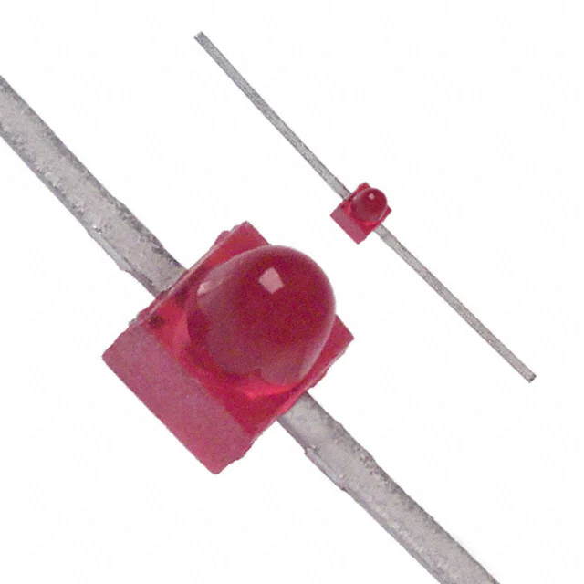
Subminiature LED Lamps
Data Sheet
Description
Features
Flat Top Package
• Subminiature flat top package
The HLMP-Pxxx Series flat top lamps use an untinted, non
diffused, truncated lens to provide a wide radiation pattern that is necessary for use in backlighting applications.
The flat top lamps are also ideal for use as emitters in light
pipe applications.
– ideal for backlighting and light piping applications
• Subminiature dome package
– diffused dome for wide viewing angle
– nondiffused dome for high brightness
Dome Packages
• TTL and LSTTL compatible 5 volt resistor lamps
The HLMP-6xxx Series dome lamps for use as indicators
use a tinted, diffused lens to provide a wide viewing angle
with a high on-off contrast ratio. High brightness lamps
use an untinted, nondiffused lens to provide a high luminous intensity within a narrow radiation pattern.
• Available in six colors
Resistor Lamps
The HLMP-6xxx Series 5 volt subminiature lamps with
built in current limiting resistors are for use in applications
where space is at a premium.
Lead Configurations
All of these devices are made by encapsulating LED chips
on axial lead frames to form molded epoxy subminiature
lamp packages. A variety of package configuration options is available. These include special surface mount
lead configurations, gull wing, yoke lead or Z-bend. Right
angle lead bends at 2.54 mm (0.100 inch) and 5.08 mm
(0.200 inch) center spacing are available for through hole
mounting. For more information refer to Standard SMT
and Through Hole Lead Bend Options for Subminiature
LED Lamps data sheet.
• Ideal for space limited applications
• Axial leads
• Available with lead configurations for surface mount
and through hole PC board mounting
�Device Selection Guide
Part Number: HLMP-xxxx
DH AS
High High
Device
Standard
AlGaAs
Efficiency Perf.
Emerald
Outline
Red
Red
Red
Orange
Yellow
Green Green
Device Description[1] Drawing
P005 P105 P205 P405 P305 P505
P605 Untinted, Nondiffused,
Flat Top
A
P102
P202
P402
P302
P502
Untinted, Diffused, Flat Top
A
6000
Q100
6300
Q400
6400
6500
Tinted, Diffused
B
Q600
Q105
6305
Q405
6405
6505
Q605
Untinted, Nondiffused,
High Brightness
B
Q150
Tinted, Diffused, Low Current
B
Q155
Nondiffused, Low Current
B
6600
6700
6800
Tinted, Diffused, Resistor,
5 V, 10 mA
B
Diffused, Resistor, 5 V, 4 mA
B
7000
6620
Ordering Information
HLMX-XXXX-X X X X X
Packaging
Option
Color Bin
Selection
Max. Iv Bin
Min. Iv Bin
4 x 4 Prod.
Part Number
2
7019
6720
7040
6820
�Package Dimensions
(B) Diffused and Nondiffused
(A) Flat Top Lamps
0.50 (0.020) REF.
1.40 (0.055)
1.65 (0.065)
11.68 (0.460)
10.67 (0.420)
BOTH SIDES
0.20 (0.008) MAX.
11.68 (0.460)
10.67 (0.420)
BOTH SIDES
CATHODE
0.46 (0.018)
0.56 (0.022)
ANODE
1.65 (0.065)
DIA.
1.91 (0.075)
0.50 (0.020) REF.
0.46 (0.018)
0.56 (0.022)
ANODE
1.65 (0.065)
DIA.
1.91 (0.075)
0.25 (0.010) MAX.
NOTE 2
0.20 (0.008) MAX.
2.21 (0.087)
1.96 (0.077)
1.14 (0.045)
1.40 (0.055)
CATHODE
0.18 (0.007)
0.23 (0.009)
0.25 (0.010) MAX.
NOTE 2
2.21 (0.087)
1.96 (0.077)
0.76 (0.030) R.
0.89 (0.035)
0.94 (0.037)
1.24 (0.049)
2.03 (0.080)
1.78 (0.070)
0.63 (0.025)
0.38 (0.015)
2.44 (0.096)
1.88 (0.074)
0.18 (0.007)
0.23 (0.009)
2.92 (0.115)
MAX.
0.79 (0.031) MAX.
2.08 (0.082)
2.34 (0.092)
0.79 (0.031)
0.53 (0.021)
0.63 (0.025)
0.38 (0.015)
2.08 (0.082)
2.34 (0.092)
CATHODE
STRIPE
CATHODE
STRIPE
NOTES:
1. ALL DIMENSIONS ARE IN MILLIMETRES (INCHES).
2. PROTRUDING SUPPORT TAB IS CONNECTED TO CATHODE LEAD.
3. LEAD POLARITY FOR AlGaAs LAMPS IS OPPOSITE TO THE LEAD
POLARITY OF SUBMINIATURE LAMPS USING OTHER TECHNOLOGIES.
CATHODE
TAB
NO. ANODE DOWN.
YES. CATHODE DOWN.
Figure 1. Proper right angle mounting to a PC board to prevent protruding cathode tab from shorting to anode connection.
HLMP-PXXX Anode/Cathode
3
�Absolute Maximum Ratings at TA = 25°C
Standard
Parameter
Red
DH AS
AlGaAs
Red
High
Eff.
High Perf.
Red Orange Yellow Green
Emerald
Green
Units
DC Forward Current[1] 50 30 30
30
20 30 30 mA
Peak Forward Current[2] 1000 300 90 90 60 90
90
mA
DC Forward Voltage
(Resistor Lamps Only)
6
6
6
6
V
Reverse Voltage (IR = 100 µA)
5
5
5
5
V
5
5
5
Transient Forward Current[3]
2000 500 500
500
500 500 500 mA
(10 µs Pulse)
Operating Temperature Range:
Non-Resistor Lamps
-55 to +100 -40 to +100
55 to +100
-40 to +100 -20 to +100 °C
Resistor Lamps
-40 to +85
Storage Temperature Range
-55 to +100
For Thru Hole Devices
Wave Soldering Temperature
[1.6 mm (0.063 in.) from body]
For Surface Mount Devices:
Reflow Soldering Temperature
-20 to +85
°C
260°C for 5 seconds
260°C for 20 seconds
Notes:
1. See Figure 5 for current derating vs. ambient temperature. Derating is not applicable to resistor lamps.
2. Refer to Figure 6 showing Max. Tolerable Peak Current vs. Pulse Duration to establish pulsed operating conditions.
3. The transient peak current is the maximum non-recurring peak current the device can withstand without failure. Do not operate these lamps at
this high current.
4
�Electrical/Optical Characteristics, TA = 25°C
Standard Red
Device
HLMP-
Parameter
Symbol
6000-E00xx
6000-G00xx
Luminous Intensity[1] I
V
Min.
Typ.
0.63
1.2
1.60 3.2
P005-F00xx
1.0
Units
Test Conditions
mcd IF = 10 mA
2.5
VF
1.4 1.6 2.0 V
IF = 10 mA
All
Reverse Breakdown
Voltage
VR
5.0
IR = 100 µA
6000
Included Angle Between
2q1/2
P005
Half Intensity Points[2]
Peak Wavelength
lPEAK
655
nm
Dominant Wavelength[3]
ld
640
nm
Spectral Line Half Width
Dl1/2
24
nm
All
Speed of Response
ts
15
ns
Capacitance
C
100
pF
VF = 0; f = 1 MHz
Thermal Resistance
RqJ-PIN
170
°C/W
Junction-to-Cathode Lead
Luminous Efficacy[4]
hv
65
lm/W
5
Forward Voltage
Max.
12.0
V
90
Deg.
125
�DH AS AlGaAs Red
Device
HLMP-
Parameter
Symbol
Min.
Typ.
Max.
P102-F00xx
1.0 20.0
P105-L00xx
10.0 30.0
P105-NP000
25
Q100-M00xx
16
Q100-N00xx
25.0 45.0
Luminous Intensity
IV
Units
80
45
Q100-PQ000
40
Q105-P00xx
40 200
Q105-ST000
160
Test Conditions
mcd
IF = 20 mA
125
500
Q150-F00xx 1.0
1.8 IF = 1 mA
Q155-F00xx
Q100
Forward Voltage
1.0 4.0
VF
1.8 2.2 V
IF = 20 mA
Q150/Q155
1.6
1.8 IF = 1 mA
All
Reverse Breakdown Voltage
VR
5.0 15.0
P105
125
Included Angle Between
1
Q100/Q150
2q /2
90
Half Intensity Points[2]
Q105/Q155
28
V
IR = 100 µA
Deg.
Peak Wavelength
lPEAK
645
nm
Dominant Wavelength[3]
ld
637
nm
Spectral Line Half Width
Dl1/2
20
nm
Measured at Peak
All
Speed of Response
ts
30
ns
Exponential Time
Constant; e-t/ts
Capacitance
C
30
pF VF = 0; f = 1 MHz
Thermal Resistance
RqJ-PIN
170
°C/W
Luminous Efficacy[4]
hv
80
lm/W
6
Junction-to Cathode Lead
�High Efficiency Red
Device
HLMP-
Parameter
Symbol
P202-F00xx
Min.
Typ.
Max.
Units
Test Conditions
1.0 5.0
P205-F00xx 1.0
8.0 IF = 10 mA
6300-F00xx
6300-KL000
Luminous Intensity[1] IV
6305-L00xx
1.0 10.0
6.3
20.0 mcd
10.0 40.0
7000-D00xx 0.4
1.0 IF = 2 mA
6600-G00xx 1.6
5.0 VF = 5.0 Volts
6620-F00xx
1.0 2.0
All
Forward Voltage
(Nonresistor Lamps)
VF
1.5 1.8 3.0 V
6600
Forward Current
IF
6620
(Resistor Lamps)
All
Reverse Breakdown Voltage
VR
IF = 10 mA
9.6 13.0 mA VF = 5.0 V
3.5 5.0
5.0 30.0
P205 125
Included Angle Between
6305
2q1/2 28
Half Intensity Points[2]
All Diffused
90
V
IR = 100 µA
Deg.
Peak Wavelength
lPEAK
635
nm
Dominant Wavelength[3]
ld
626
nm
Spectral Line Half Width
Dl1/2
40
nm
All
Speed of Response
ts
90
ns
Capacitance
C
11
pF VF = 0; f = 1 MHz
Thermal Resistance
RqJ-PIN
170
°C/W
Luminous Efficacy[4]
hv
145
lm/W
7
Measured at Peak
Junction-to-Cathode Lead
�Orange
Device
HLMP-
Parameter
Symbol
Min.
Typ.
Max.
Units
P402-F00xx
1.0 4.0
P405-F00xx
1.0 6
P405-JK000
4.0
Luminous Intensity
IV
Test Conditions
12.5 mcd IF = 10 mA
Q400-F00xx
1.0 8
Q405-H00xx
2.5 14
All
Forward Voltage
VF
1.5 1.9 3.0 V
IF = 10 mA
Reverse Breakdown Voltage
VR
5.0 30.0
IR = 100 µA
P40x
Included Angle Between
2q1/2
Q40x
Half Intensity Points[2]
Peak Wavelength
lPEAK
600
nm
Dominant Wavelength[3]
ld
602
nm
Spectral Line Half Width
Dl1/2
40
nm
All
Speed of Response
ts
260
ns
Capacitance
C 4
pF VF = 0; f = 1 MHz
Thermal Resistance
RqJ-PIN
170
°C/W
Luminous Efficacy[4]
hv
380
lm/W
8
125
V
Deg.
90
Measured at Peak
Junction-to-Cathode Lead
�Yellow
Device
HLMP-
Parameter
Symbol
Min.
Typ.
Max.
Units
P302-F00xx
1.0 3.0
P305-F00xx
1.0 4.0
6400-F00xx
1.0 9.0
6400-JK000
4.0
6405-J00xx
Luminous Intensity[1] IV
6405-MN0xx
12.5
3.6 20
16
Test Conditions
IF = 10 mA
mcd
50
7019-D00xx 0.4
0.6 IF = 2 mA
6700-G00xx 1.4
5.0 VF = 5.0 Volts
6720-F00xx
0.9 2.0
All
Forward Voltage
(Nonresistor Lamps)
VF
2.0 2.4 V
6700
Forward Current
IF
9.6 13.0 mA VF = 5.0 V
6720
(Resistor Lamps)
All
Reverse Breakdown
Voltage
VR
3.5 5.0
5.0 50.0
P305
Included Angle Between
125
6405
Half Intensity Points[2] 2q1/2
28
All Diffused
IF = 10 mA
V
Deg.
90
Peak Wavelength
lPEAK
583
nm
Dominant Wavelength[3]
ld
585
nm
Spectral Line Half Width
Dl1/2
36
nm
All
Speed of Response
ts
90
ns
Capacitance
C
15
pF VF = 0; f = 1 MHz
Thermal Resistance
RqJ-PIN
170
°C/W
Luminous Efficacy[4]
hv
500
lm/W
9
Measured at Peak
Junction-to-Cathode Lead
�High Performance Green
Device
HLMP-
Parameter
Symbol
P502-F00xx
Min.
Typ.
Max.
Units
Test Conditions
1.0 3.0
P505-G00xx 1.6
6.3 IF = 10 mA
6500-F00xx
6505-L00xx
Luminous Intensity[1] Iv
1.0 7.0
10.0 40.0
mcd
7040-D00xx 0.4
0.6 IF = 2 mA
6800-G00xx 1.6
5.0 VF = 5.0 Volts
6820-F00xx
1.0 2.0
All
Forward Voltage
(Nonresistor Lamps)
VF
2.1 2.7 V
6800
Forward Current
IF
9.6 13.0 mA VF = 5.0 V
6820
(Resistor Lamps)
All
Reverse Breakdown Voltage
P505
Included Angle Between
125
6505
Half Intensity Points[2] 2q1/2
28
VR
3.5 5.0
5.0 50.0
All Diffused
IF = 10 mA
V
IR = 100 µA
Deg.
90
Peak Wavelength
lPEAK
565
nm
Dominant Wavelength[3]
ld
569
nm
Spectral Line Half Width
Dl1/2
28
nm
All
Speed of Response
ts
500
ns
Capacitance
C
18
pF VF = 0; f = 1 MHz
Thermal Resistance
RqJ-PIN
170
°C/W
Luminous Efficacy[4]
hv
595
lm/W
Junction-to-Cathode Lead
Notes:
1. The luminous intensity for arrays is tested to assure a 2.1 to 1.0 matching between elements. The average luminous intensity for an array determines
its light output category bin. Arrays are binned for luminous intensity to allow Iv matching between arrays.
2. q1/2 is the off-axis angle where the luminous intensity is half the on-axis value.
3. Dominant wavelength, ld, is derived from the CIE Chromaticity Diagram and represents the single wavelength that defines the color of the device.
4. Radiant intensity, Ie, in watts/steradian, may be calculated from the equation Ie = Iv/hv, where Iv is the luminous intensity in
candelas and hv is the luminous efficacy in lumens/watt.
10
�Emerald Green[1]
Device
HLMP-
Parameter
Symbol
Min.
Typ.
Max.
P605-F00xx
1.0 1.5
Q600-F00xx
1.0 1.5
Luminous Intensity
IV
Q605-F00xx
Units
Test Conditions
mcd IF = 10 mA
1.0 7.5
All
Forward Voltage
VF
2.2 3.0 V
Reverse Breakdown Voltage
VR 5.0
V
P605
Included Angle Between
2q1/2
Deg.
Q60x
Half Intensity Points[2] 90
Peak Wavelength
lPEAK
558
nm
Dominant Wavelength[3]
ld
560
nm
Spectral Line Half Width
Dl1/2
24
nm
P605/Q600
Speed of Response
ts
3100
ns
Capacitance
C
35
pF VF = 0; f = 1 MHz
Thermal Resistance
RqJ-PIN
170
°C/W
Luminous Efficacy[4]
hV
656
lm/W
125
IF = 10 mA
IR = 100 µA
Measured at Peak
Junction-to-Cathode Lead
Note:
1. Please refer to Application Note 1061 for information comparing standard green and emerald green light output degradation.
11
�Figure 1. Relative intensity vs. wavelength.
Standard Red and DH AS
AlGaAs Red
High Efficiency Red, Orange, Yellow, High
Performance Green, and Emerald Green
100
FORWARD CURRENT – mA
90
HIGH EFFICIENCY
RED/ORANGE
80
70
60
YELLOW
50
40
30
HIGH
PERFORMANCE
GREEN,
EMERALD
GREEN
20
10
0
0
0.5
1
1.5
2
2.5
3
3.5
FORWARD VOLTAGE – V
Figure 2. Forward current vs. forward voltage (non-resistor lamp).
Standard Red, DH As AlGaAs Red
Figure 3. Relative luminous intensity vs. forward current (non-resistor lamp).
12
HLMP-PXXX fig 2b
Low Current
HER, Orange, Yellow, and
High Performance Green,
and Emerald Green
�Standard Red
DH As AlGaAs Red
HER, Orange, Yellow, and
High Performance Green,
and Emerald Green
Figure 4. Relative efficiency (luminous intensity per unit current) vs. peak current (non-resistor lamps).
Figure 5. Maximum forward dc current vs. ambient temperature. Derating based on TJ MAX = 110°C (non-resistor lamps).
Standard Red
HER, Orange, Yellow, and High Performance
Green
Figure 6. Maximum tolerable peak current vs. pulse duration (IDC MAX as per MAX ratings) (non-resistor lamps).
13
DH As AlGaAs Red
�Figure 7. Resistor lamp forward current vs. forward voltage.
Figure 9. Relative intensity vs. angular displacement.
14
Figure 8. Resistor lamp luminous intensity vs. forward voltage.
�Ordering Information
Color Bin Limits
HLMx-XXXX-X X X X X
Package
Bin
Min.
Emerald Green
0
Full Distribution
9
552
556
8
555
559
7
558
562
6
561
565
Green
0
Full Distribution
6
561
565
5
564
568
4
567
571
3
570
574
2
573
577
Yellow
0
Full Distribution
1
581.5
585.0
3
584.0
587.5
2
586.5
590.0
4
589.0
592.5
5
591.5
593.5
6
591.5
595.0
7
594.0
597.5
Orange
0
Full Distribution
1
596.5
600.0
2
599.0
602.5
3
601.5
604.0
4
603.8
608.2
5
606.8
611.2
6
609.8
614.2
7
612.8
617.2
8
615.8
620.2
Packaging
Option
Color Bin
Selection
Max. Iv Bin
Min. Iv Bin
4 x 4 Prod.
Part
Number
Intensity Bin Limits
Bin
Min.
Max.
A
0.10
0.20
B
0.16
0.32
C
0.25
0.50
D
0.40
0.80
E
0.63
1.25
F
1.00
2.00
G
1.60
3.20
H
2.50
5.00
J
4.00
8.00
K
6.30
12.50
L
10.00
20.00
M
16.00
32.00
N
25.00
50.00
P
40.00
80.00
Q
63.00
125.00
R
100.00
200.00
S
160.00
320.00
T
250.00
500.00
U
400.00
800.00
V
630.00
1250.00
W
1000.00
2000.00
X
1600.00
3200.00
Y
2500.00
5000.00
15
Max.
�Mechanical Option
00
Straight Leads, Bulk Packaging, Quantity of 500 Parts
10
Right Angle Housing, Bulk Packaging, Quantity of 500 Parts
11
Gull Wing Leads, 12 mm Tape on 7 in. Dia. Reel, 1500 Parts per Reel
12
Gull Wing Lead, Bulk Packaging, Quantity of 500 Parts
14
Gull Wing Leads, 12 mm Tape on 13 in. Dia. Reel, 6000 Parts per Reel
21
Yoke Leads, 12 mm Tape on 7 in. Dia. Reel, 1500 Parts per Reel
22
Yoke Leads, Bulk Packaging, Quantity of 500 Parts
24
Yoke Leads, 12 mm Tape on 13 in. Dia. Reel, 6000 Parts per Reel
31
Z-Bend Leads, 12 mm Tape on 7 in. Dia. Reel, 1500 Parts per Reel
32
Z-Bend Leads, Bulk Packaging, Quantity of 500 Parts
34
Z-Bend Leads, 12 mm Tape on 13 in. Dia. Reel, 6000 Parts per Reel
1L
2.54 mm (0.100 inch) Center Lead Spacing, Long Leads; 10.4 mm (0.410 in.)
1S
2.54 mm (0.100 inch) Center Lead Spacing, Short Leads; 3.7 mm (0.145 in.)
2L
5.08 mm (0.200 inch) Center Lead Spacing, Long Leads; 10.4 mm (0.410 in.)
2S
5.08 mm (0.200 inch) Center Lead Spacing, Short Leads; 3.7 mm (0.145 in.)
Note:
All Categories are established for classification of products. Products may not be available in all categories. Please contact your local Avago representative for further clarification/information.
For product information and a complete list of distributors, please go to our web site:
www.avagotech.com
Avago, Avago Technologies, and the A logo are trademarks of Avago Technologies in the United States and other countries.
Data subject to change. Copyright © 2005-2014 Avago Technologies. All rights reserved. Obsoletes 5989-1708EN
AV02-3609EN - December 10, 2014
�