Data Sheet
HSMF-C16x
Miniature Bi-Color Surface Mount ChipLEDs
Features
Description
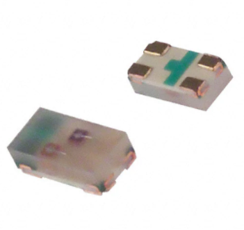
The Broadcom® HSMF-C16x series of bi-color ChipLEDs is
designed with the smallest footprint to achieve high density
of components on board. They have the industry-standard
footprint of 1.6 mm x 0.8 mm and a height of only 0.5 mm.
This makes them very suitable for cellular phone and mobile
equipment backlighting and indication. They are available in
a wide range of color combinations. In order to facilitate
automated pick and place operation, these ChipLEDs are
shipped in tape and reel, with 4000 units per reel. These
parts are compatible with reflow soldering.
Small size
0603 industry-standard footprint
Diffused optics
Operating temperature range of –40°C to +85°C
Compatible with reflow soldering
Available in various color combination
Available in 8-mm tape on 7 inch (178 mm) diameter
reels
Applications
Keypad backlighting
Symbol indicator
LCD backlighting
Pushbutton backlighting
Front-panel indicator
Device Selection Guide
Part Number
Color
Package Description
HSMF-C162
AlInGaP Red/AlInGaP Amber
Untinted, Diffused
HSMF-C163
AlInGaP Red/InGaN Green
Untinted, Diffused
HSMF-C164
AlInGaP Red/InGaN Blue
Untinted, Diffused
HSMF-C165
AlInGaP Red/AlInGaP Green
Untinted, Diffused
HSMF-C166
AlInGaP Yellow/AlInGaP Green
Untinted, Diffused
HSMF-C167
AlInGaP Orange/AlInGaP Green
Untinted, Diffused
HSMF-C169
AlInGaP Amber/InGaN Blue
Untinted, Diffused
CAUTION! The HSMF-C16x LEDs are Class 1A ESD sensitive per JESD22-A114C.01 standard. Observe appropriate
precautions during handling and processing. Refer to Application Note AN-1142 for additional details.
Broadcom
AV02-0584EN
May 13, 2022
�HSMF-C16x Data Sheet
Miniature Bi-Color Surface Mount ChipLEDs
Package Dimensions
CATHODE LINE
LED DIES
1
3
2
4
0.8 (0.031)
1.6
(0.063†)
DIFFUSED EPOXY
0.16 (0.006)
PC BOARD
0.5 (0.020)
0.4
(0.016)
CATHODE LINE
0.3 (0.012)
SOLDERING
TERMINALS
NOTE:
All Dimensions are in millimeters (inches).
Tolerance is ± 0.1 mm (± 0.004 in.) unless otherwise specified.
Polarity
Broadcom
HSMF-C162
HSMF-C163
HSMF-C164
HSMF-C165
HSMF-C166
HSMF-C167
HSMF-C169
Amber
Green
Blue
Green
Green
Green
Blue
Red
Red
Red
Red
Yellow
Orange
Amber
AV02-0584EN
2
�HSMF-C16x Data Sheet
Miniature Bi-Color Surface Mount ChipLEDs
Absolute Maximum Ratings for Each Die at TA = 25°C
Parameter
AlInGaP
InGaN
Unit
DC Forward Currenta
20
10
mA
Power Dissipation
52
38
mW
Reverse Voltage
5
5
V
LED Junction Temperature
95
95
°C
Operating and Storage Temperature Range
–40 to 85
Soldering Temperature
°C
See reflow soldering profile (Figure 6 and Figure 7)
a. Derate linearly as shown in Figure 4.
Electrical Characteristics (TA = 25°C)
Voltage,a
Forward
VF (V)
Part Number
Test Current
HSMF-C162
20 mA
HSMF-C163
HSMF-C164
HSMF-C165
HSMF-C166
HSMF-C167
HSMF-C169
10 mA
10 mA
20 mA
20 mA
20 mA
10 mA
Color
Minimum
Typical
Reverse
IR (µA) at VR = 5V
Thermal
Resistance,c
RθJ-S (°C/W)
Maximum
Typical
Current,b
Maximum
AInGaP Red
1.60
1.90
2.40
100
300
AlInGaP Amber
1.60
1.90
2.40
100
300
AlInGaP Red
1.60
1.80
2.40
100
300
InGaN Green
2.90
3.40
3.70
100
500
AlInGaP Red
1.60
1.80
2.40
100
300
InGaN Blue
2.90
3.40
3.70
100
500
AlInGaP Red
1.60
1.95
2.60
100
325
AlInGaP Green
1.60
2.20
2.60
100
325
AlInGaP Yellow
1.60
2.10
2.60
100
325
AlInGaP Green
1.60
2.20
2.60
100
325
AlInGaP Orange
1.60
2.20
2.60
100
325
AlInGaP Green
1.60
2.20
2.60
100
325
AlInGaP Amber
1.60
1.90
2.40
100
300
InGaN Blue
2.90
3.40
3.70
100
500
a. Forward voltage tolerance is ±0.1V.
b. Indicates product final test condition. Long-term reverse bias is not recommended.
c. Thermal resistance from LED junction to solder point.
Broadcom
AV02-0584EN
3
�HSMF-C16x Data Sheet
Miniature Bi-Color Surface Mount ChipLEDs
Optical Characteristics (TA = 25°C)
Luminous Intensity,
IV a (mcd)
Part Number
HSMF-C162
HSMF-C163
HSMF-C164
HSMF-C165
HSMF-C166
HSMF-C167
HSMF-C169
Test Current Color
20 mA
10 mA
10 mA
20 mA
20 mA
20 mA
10 mA
Minimum
Dominant
Wavelength,
d b (nm)
Peak Wavelength,
p (nm)
Viewing Angle
2θ1/2 c(Degrees)
Typical
Typical
Typical
Typical
AInGaP Red
28.5
90.0
626
637
120
AlInGaP Amber
28.5
90.0
592
595
120
AlInGaP Red
11.2
35.0
626
637
120
InGaN Green
18.0
45.0
525
523
120
AlInGaP Red
11.2
35.0
626
637
120
InGaN Blue
2.80
10.0
470
468
120
AlInGaP Red
2.80
10.0
621
636
120
AlInGaP Green
4.50
15.0
572
570
120
AlInGaP Yellow
2.80
8.0
586
589
120
AlInGaP Green
4.50
15.0
572
570
120
AlInGaP Orange
2.80
8.0
604
605
120
AlInGaP Green
4.50
15.0
572
570
120
AlInGaP Amber
28.5
90.0
592
595
120
InGaN Blue
2.80
10.0
470
468
120
a. The luminous intensity, IV, is measured at the mechanical axis of the package, and it is tested with a single current pulse condition. The actual
peak of the spatial radiation pattern may not be aligned with the axis.
b. The dominant wavelength, d, is derived from the CIE Chromaticity Diagram and represents the perceived color of the device.
c.
½ is the off-axis angle where the luminous intensity is one half the peak intensity.
Color Bin Limits1
Green Color Bins
Dominant Wavelength (nm)
Bin ID
Minimum
Maximum
A
561.5
564.5
B
564.5
567.5
C
567.5
570.5
D
570.5
573.5
E
573.5
576.5
Tolerance: ±0.5 nm.
1.
Broadcom
Bin categories are established for classification of products. Products may not be available in all categories. Contact your
Broadcom representative for information on current available bins.
AV02-0584EN
4
�HSMF-C16x Data Sheet
Miniature Bi-Color Surface Mount ChipLEDs
InGaN Blue Color Bins
InGaN Green Color Bins
Dominant Wavelength (nm)
Dominant Wavelength (nm)
Bin ID
Minimum
Maximum
Bin ID
Minimum
Maximum
A
460.0
465.0
A
515.0
520.0
B
465.0
470.0
B
520.0
525.0
C
470.0
475.0
C
525.0
530.0
D
475.0
480.0
D
530.0
535.0
Tolerance: ±1 nm.
Tolerance: ±1 nm.
Orange Color Bins
Light Intensity (IV) Bin Limits
Dominant Wavelength (nm)
Intensity (mcd)
Bin ID
Minimum
Maximum
Bin ID
Minimum
Maximum
A
597.0
600.0
B
600.0
603.0
A
0.11
0.18
B
0.18
0.29
C
603.0
D
606.0
606.0
C
0.29
0.45
609.0
D
0.45
0.72
E
F
609.0
612.0
E
0.72
1.10
612.0
615.0
F
1.10
1.80
G
1.80
2.80
H
2.80
4.50
J
4.50
7.20
K
7.20
11.20
Tolerance: ±1 nm.
Amber/Yellow Color Bins
Dominant Wavelength (nm)
L
11.20
18.00
M
18.00
28.50
Bin ID
Minimum
Maximum
N
28.50
45.00
A
582.0
584.5
P
45.00
71.50
B
584.5
587.0
Q
71.50
112.50
C
587.0
589.5
R
112.50
180.00
D
589.5
592.0
S
180.00
285.00
285.00
450.00
E
592.0
594.5
T
F
594.5
597.0
U
450.00
715.00
V
715.00
1125.00
Tolerance: ±0.5 nm.
W
1125.00
1800.00
Red Color Bins
X
1800.00
2850.00
Y
2850.00
4500.00
Dominant Wavelength (nm)
Bin ID
Minimum
Maximum
–
620.0
635.0
Tolerance: ±15%.
Tolerance: ±1 nm
Broadcom
AV02-0584EN
5
�HSMF-C16x Data Sheet
Miniature Bi-Color Surface Mount ChipLEDs
Figure 1: Relative Intensity versus Wavelength
RELATIVE INTENSITY – %
100
90
InGaN
BLUE
80
InGaN
GREEN
70
60
50
40
30
20
10
0
400
450
550
600
500
WAVELENGTH – nm
650
700
Figure 2: Forward Current versus Forward Voltage
IF – FORWARD CURRENT – mA
100
InGaN
10
1
0.1
1.5
2.5
3.5
2.0
3.0
VF – FORWARD VOLTAGE – V
4.0
Figure 3: Luminous Intensity versus Forward Current
1.6
AllnGaP
LUMINOUS INTENSITY
(NORMALIZED AT 10 mA)
1.4
1.2
1.0
0.8
InGaN
0.6
0.4
0.2
0
Broadcom
0
2
4
6
8
10 12 14
IF – FORWARD CURRENT – mA
16
AV02-0584EN
6
�HSMF-C16x Data Sheet
Miniature Bi-Color Surface Mount ChipLEDs
Figure 4: Maximum Forward Current versus Ambient
Temperature
100
25
90
AlInGaP
20
80
RELATIVE INTENSITY – %
IF MAX. – MAXIMUM FORWARD CURRENT – mA
Figure 5: Relative Intensity versus Angle
15
InGaN
10
60
50
40
30
20
5
0
70
10
0
-90 -80 -70 -60 -50 -40 -30 -20 -10
0
10 20 30 40 50 60 70 80 90 100
TA – AMBIENT TEMPERATURE – °C
Figure 6: Recommended Reflow Soldering Profile
0 10
ANGLE
20
30
40
50
60
70
80 90
Figure 7: Recommended Pb-free Reflow Soldering Profile
10 - 30 SEC.
TEMPERATURE
230°C MAX.
4°C/SEC. MAX.
140-160°C
3°C/SEC. MAX.
4°C/SEC.
MAX.
OVER 2 MIN.
TEMPERATURE
10 SEC. MAX.
217°C
200°C
255 - 260°C
3°C/SEC. MAX.
6°C/SEC. MAX.
150°C
3°C/SEC. MAX.
100 SEC. MAX.
60 - 120 SEC.
TIME
TIME
(Acc. to J-STD-020C)
Figure 8: Recommended Solder Pad Pattern
0.60
(0.024)
0.40
(0.016)
0.30
(0.012)
0.70
(0.028)
NOTE:
Broadcom
0.70
(0.028)
0.40
(0.016)
All dimensions are in millimeters (inches).
AV02-0584EN
7
�HSMF-C16x Data Sheet
Miniature Bi-Color Surface Mount ChipLEDs
Figure 9: Reeling Orientation
USER FEED DIRECTION
CATHODE SIDE
xxx
xxxxx
xxxxx
xxxxx
xxxxx
xx
PRINTED LABEL
Figure 10: Reel Dimensions
8.0 ± 1.0 (0.315 ± 0.039)
10.50 ± 1.0 (0.413 ± 0.039)
Ø 13.1 ± 0.5
(Ø 0.516 ± 0.020)
Ø 20.20 MIN.
(Ø 0.795 MIN.)
3.0 ± 0.5
(0.118 ± 0.020)
59.60 ± 1.00
(2.346 ± 0.039)
178.40 ± 1.00
(7.024 ± 0.039)
4.0 ± 0.5
(0.157 ± 0.020)
NOTE:
Broadcom
6
PS
5.0 ± 0.5
(0.197 ± 0.020)
All dimensions are in millimeters (inches).
AV02-0584EN
8
�HSMF-C16x Data Sheet
Miniature Bi-Color Surface Mount ChipLEDs
Figure 11: Tape Dimensions
4.00 (0.157)
DIM. C
(SEE TABLE 1)
CATHODE
1.50 (0.059)
0.20 ± 0.05
(0.008 ± 0.002)
1.75 (0.069)
3.50 ± 0.05
(0.138 ± 0.002)
DIM. A
(SEE TABLE 1)
DIM. B
(SEE TABLE 1)
8.00 ± 0.30
(0.315 ± 0.012)
2.00 ± 0.05
(0.079 ± 0.002)
CARRIER TAPE
USER FEED
DIRECTION
COVER TAPE
4.00 (0.157)
TABLE 1
DIMENSIONS IN MILLIMETERS (INCHES)
PART NUMBER
DIM. A
± 0.10 (± 0.004)
DIM. B
± 0.10 (± 0.004)
DIM. C
± 0.10 (± 0.004)
HSMF-C16x
1.75 (0.069)
0.95 (0.037)
0.60 (0.024)
Figure 12: Tape Leader and Trailer Dimensions
END
START
THERE SHALL BE A MINIMUM
OF 160 mm (6.3 INCH) OF
EMPTY COMPONENT POCKETS
SEALED WITH COVER TAPE.
NOTE:
MOUNTED WITH
COMPONENTS.
THERE SHALL BE A MINIMUM
OF 160 mm (6.3 INCH) OF
EMPTY COMPONENT POCKETS
SEALED WITH COVER TAPE.
MINIMUM OF
230 mm (9.05 INCH)
MAY CONSIST OF
CARRIER AND/OR
COVER TAPE.
All dimensions are in millimeters (inches).
Tolerance is ±0.1 mm (±0.004 in.) unless otherwise specified.
Broadcom
AV02-0584EN
9
�HSMF-C16x Data Sheet
Miniature Bi-Color Surface Mount ChipLEDs
Precautionary Notes
Soldering
Handling Precautions
Do not perform reflow soldering more than twice.
Observe necessary precautions of handling
moisture-sensitive devices as stated in the following
section.
Do not apply any pressure or force on the LED during
reflow and after reflow when the LED is still hot.
Use reflow soldering to solder the LED. Use hand
soldering only for rework if unavoidable, but it must be
strictly controlled to following conditions:
– Soldering iron tip temperature = 310°C maximum.
– Soldering duration = 2 seconds maximum.
– Number of cycles = 1 only.
– Power of soldering iron = 50W maximum.
Do not touch the LED package body with the soldering
iron, except for the soldering terminals, because it may
cause damage to the LED.
Confirm beforehand whether the functionality and
performance of the LED is affected by soldering with
hand soldering.
Figure 13: Recommended Lead-Free Reflow Soldering Profile
This product has a Moisture Sensitive Level 2a rating per
JEDEC J-STD-020. Refer to Broadcom Application Note
AN5305, Handling of Moisture Sensitive Surface Mount
Devices, for additional details and a review of proper
handling procedures.
Before use:
An unopened moisture barrier bag (MBB) can be stored
at
很抱歉,暂时无法提供与“HSMF-C165”相匹配的价格&库存,您可以联系我们找货
免费人工找货- 国内价格
- 5+3.74934
- 50+2.71709
- 250+2.25435
- 1000+2.10011
- 2000+1.98146
- 国内价格
- 1000+2.83257
- 2000+2.77217
- 国内价格 香港价格
- 4000+1.906654000+0.24667
- 8000+1.810268000+0.23420
- 12000+1.7608412000+0.22781
- 20000+1.7050820000+0.22059
- 28000+1.6719128000+0.21630
- 40000+1.6395940000+0.21212