HSMR-C170-R0000
Blue ChipLED
Data Sheet
Description
Features
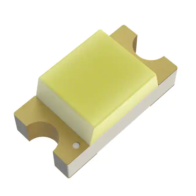
The HSMR-C170-R0000 ChipLED is a surface-mount LED that
comes in an industrial standard 2.0 mm × 1.25 mm package
footprint, which allows for ease of use and handling. It offers
industry-leading performance by using efficient and high
brightness InGaN material.
This LED has a wide viewing angle. Coupled with high
performance, these features make this device an ideal
candidate for applications that require uniform light
distribution and high brightness.
LED with InGaN die
Surface-mount device with 0805 footprint
0.8-mm package height
Compatible with reflow soldering
Tape in 8-mm carrier tape on a 7-in. diameter reel
Applications
This device is ideal for use in applications, such as industrial
equipment, consumer electronics, gaming, home appliances,
and black and white goods markets.
Pushbutton backlighting
Icon backlighting
Status indicator
CAUTION: LEDs are Class 1A ESD sensitive per ANSI/ESDA/JEDEC JS-001. Observe appropriate precautions during handling and
processing. Refer to Application Note AN-1142 for additional details.
Broadcom
-1-
�HSMR-C170-R0000
Data Sheet
Package Dimensions
NOTE
1.
2.
All dimensions are in millimeters (in.).
Tolerance ±0.1 mm (±0.004 in.) unless otherwise specified.
Broadcom
-2-
�HSMR-C170-R0000
Data Sheet
Absolute Maximum Value at TJ = 25°C
Parameter
Rating
Unit
DC Forward Currenta
20
mA
Peak Forward Currentb
100
mA
Power Dissipation
78
mW
LED Junction Temperature
95
°C
Operating Temperature Range
–40 to +85
°C
Storage Temperature Range
–40 to +85
°C
a.
Derate as shown in Figure 7.
b.
Duty factor = 10%, frequency = 1 KHz.
Optical/Electrical Characteristics at TJ = 25°C, IF=20 mA
Parameter
Min.
Typ.
Max.
Unit
146.25
170.00
1125.00
mcd
Dominant Wavelength, db
—
466
—
nm
Peak Wavelength, p
—
462
—
nm
Viewing Angle, 2½c
—
155
—
degree
Forward Voltage, Vf
Luminous Intensity, Iva
2.9
—
3.9
V
Reverse Voltage, Vrd at Ir = 100 μA
5
—
—
V
Thermal Resistance, Rj-s
—
300
—
°C/W
a.
The luminous intensity is measured at the mechanical axis of the LED package. The actual peak of the
spatial radiation pattern may not be aligned with the axis.
b.
The dominant wavelength is derived from the CIE chromaticity diagram and represents the perceived
color of the device.
c.
The viewing angle is the off-axis angle where the luminous intensity is ½ the peak intensity.
d.
Indicates product final test condition. Long- term reverse bias is not recommended.
Broadcom
-3-
�HSMR-C170-R0000
Data Sheet
Bin Information
Color Bins (BIN)
Intensity Bins (CAT)
Dominant Wavelength (nm)
Luminous Intensity (mcd)
Bin ID
Bin ID
R2
Min.
Max.
Min.
Max.
146.25
180.00
A
460
465
465
470
S
180.00
285.00
B
T
285.00
450.00
C
470
475
U
450.00
715.00
D
475
480
V
715.00
1125.00
Tolerance = ± 1 nm.
Tolerance = ± 15%.
Forward Voltage Bins
Forward Voltage (V)
Bin ID
Min.
Max.
1
2.9
3.1
2
3.1
3.3
3
3.3
3.5
4
3.5
3.7
5
3.7
3.9
Tolerance = ± 0.1V.
Broadcom
-4-
�HSMR-C170-R0000
Data Sheet
Figure 1 Spectrum
Figure 2 Relative Intensity vs. Forward Current
Figure 3 Forward Current vs. Forward Voltage
Figure 4 Radiation Pattern
Figure 5 Dominant Wavelength Shift vs. Forward Current
Figure 6 Relative Intensity vs. Temperature
Broadcom
-5-
�HSMR-C170-R0000
Figure 7 Derating Curve
Data Sheet
Recommended Solder Pad
Reel Orientation
Broadcom
-6-
�HSMR-C170-R0000
Data Sheet
Reel Dimensions
Carrier Tape Dimensions
Broadcom
-7-
�HSMR-C170-R0000
Data Sheet
Soldering
Precautionary Notes
Figure 8 Recommended Reflow Soldering Condition
Handling of Moisture-Sensitive Devices
This product has a Moisture Sensitive Level 2a rating per JEDEC
J-STD-020. Refer to Broadcom Application Note AN5305,
Handling of Moisture Sensitive Surface Mount Devices, for
additional details and a review of proper handling procedures.
Temperature
10s max.
217°C
200°C
255°C to 260°C
3 °C/s max.
6 °C/s max.
150°C
3 °C/s max.
60s max.
60s to 120s
Time
Do not perform reflow soldering more than twice. Observe
necessary precautions when handling moisture-sensitive
device as stated in the next section.
Do not apply any pressure or force on the LED during
reflow and after reflow while the LED is still hot.
Use reflow soldering to solder the LED. But if it is
unavoidable (such as rework), manual hand soldering may
be used but must be strictly controlled to the following
conditions:
— Soldering iron tip temperature = 310°C max.
— Soldering duration = 2s max.
— Number of cycles = One only
— Power of the soldering iron = 50W max.
Do not touch the LED package body with the soldering
iron except for the soldering terminals as it might damage
the LED.
Confirm beforehand whether the functionality and
performance of the LED is affected by hand soldering.
Before use:
— An unopened moisture barrier bag (MBB) can be
stored at < 40°C / 90% RH for 12 months. If the actual
shelf life has exceeded 12 months and the humidity
indicator card (HIC) indicates that baking is not
required, it is safe to reflow the LEDs per the original
MSL rating.
— Do not open the MBB prior to assembly (for example,
for IQC).
Control after opening the MBB:
— Read the HIC immediately upon opening the MBB.
— Keep the LEDs < 30°C / 60% RH at all times, and
complete all high temperature-related processes, such
as soldering, curing, or rework, within 672 hours.
Control for unfinished reel:
Store unused LEDs in a sealed MBB with desiccant or
desiccator at < 5% RH.
Control of assembled boards:
If the PCB soldered with the LEDs is to be subjected to
other high temperature processes, store the PCB in a
sealed MBB with desiccant or desiccator at < 5% RH to
ensure that all LEDs have not exceeded their floor life of
672 hours.
Baking is required if the following conditions exist:
— The HIC indicator is not blue at 10% and is pink at 5%.
— The LEDs are exposed to conditions of > 30°C / 60% RH
at any time.
— The LED floor life exceeded 672 hours.
The recommended baking condition is: 60°C ± 5ºC for
20 hours.
Bake the LED only once.
Broadcom
-8-
�HSMR-C170-R0000
Data Sheet
Application Precautions
Eye Safety Precautions
The drive current of the LED must not exceed the
maximum allowable limit across temperature as stated in
the data sheet. Constant current driving is recommended
to ensure consistent performance.
Circuit design must cater for the entire range of forward
voltage (VF) of the LEDs to ensure that the intended drive
current can always be achieved.
If the LED is to be used with an LED of another color to
achieve color mixing, Broadcom does not guarantee the
consistency of the resultant color. Contact a Broadcom
sales representative for these applications.
The LED exhibits slightly different characteristics at
different drive currents, which might result in larger
variation of its performance (for example, intensity,
wavelength, and forward voltage). Set the application
current as close as possible to the test current to minimize
these variations.
The LED is not intended for reverse bias. Use other
appropriate components for such purposes. When driving
the LED in matrix form, ensure that the reverse bias voltage
does not exceed the allowable limit of the LED.
Avoid rapid change in ambient temperatures, especially in
high-humidity environments, because they cause
condensation on the LED.
If the LED is to be used in harsh environments, protect the
LED against damages caused by rain water, dust, oil,
corrosive gases, external mechanical stress, and so on.
LEDs may pose optical hazards when in operation. Do not look
directly at operating LEDs because it might be harmful to the
eyes. For safety reasons, use appropriate shielding or personal
protection equipment.
Broadcom
-9-
�Disclaimer
Broadcom’s products are not specifically designed, manufactured, or authorized for sale as parts, components, or assemblies for the
planning, construction, maintenance, or direct operation of a nuclear facility or for use in medical devices or applications. The
customer is solely responsible, and waives all rights to make claims against Broadcom or its suppliers, for all loss, damage, expense,
or liability in connection with such use.
For product information and a complete list of distributors, please go to our web site:
www.broadcom.com.
Broadcom, the pulse logo, Connecting everything, Avago Technologies, Avago, and
the A logo are among the trademarks of Broadcom and/or its affiliates in the United
States, certain other countries and/or the EU.
Copyright © 2016 by Broadcom. All Rights Reserved.
The term "Broadcom" refers to Broadcom Limited and/or its subsidiaries. For more
information, please visit www.broadcom.com.
Broadcom reserves the right to make changes without further notice to any
products or data herein to improve reliability, function, or design.
Information furnished by Broadcom is believed to be accurate and reliable. However,
Broadcom does not assume any liability arising out of the application or use of this
information, nor the application or use of any product or circuit described herein,
neither does it convey any license under its patent rights nor the rights of others.
HSMR-C170-R0000-DS100 – December 16, 2016
�