HSMS-286x Series
Surface Mount Microwave Schottky Detector Diodes
Data Sheet
Description
Features
Avago’s HSMS‑286x family of DC biased detector diodes
have been designed and optimized for use from 915 MHz
to 5.8 GHz. They are ideal for RF/ID and RF Tag applications
as well as large signal detection, modulation, RF to DC
conversion or voltage doubling.
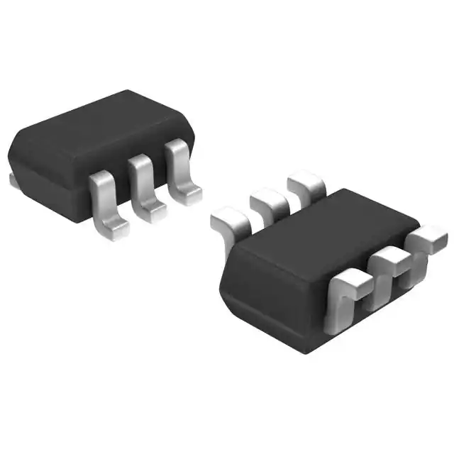
• Surface Mount SOT-23/SOT‑143 Packages
Available in various package configurations, this family
of detector diodes provides low cost solutions to a wide
variety of design problems. Avago’s manufacturing
techniques assure that when two or more diodes are
mounted into a single surface mount package, they
are taken from adjacent sites on the wafer, assuring the
highest possible degree of match.
Pin Connections and Package Marking
6
PLx
1
2
3
5
4
Notes:
1. Package marking provides orientation and identification.
2. The first two characters are the package marking code.
The third character is the date code.
• Miniature SOT-323 and SOT‑363 Packages
• High Detection Sensitivity:
up to 50 mV/µW at 915 MHz
up to 35 mV/µW at 2.45 GHz
up to 25 mV/µW at 5.80 GHz
• Low FIT (Failure in Time) Rate*
• Tape and Reel Options Available
• Unique Configurations in Surface Mount SOT-363
Package
– increase flexibility
– save board space
– reduce cost
• HSMS-286K Grounded Center Leads Provide up to
10 dB Higher Isolation
• Matched Diodes for Consistent Performance
• Better Thermal Conductivity for Higher Power
Dissipation
• Lead-free
* For more information see the Surface Mount Schottky Reliability
Data Sheet.
SOT-323 Package Lead Code Identification (top view)
SOT-23/SOT-143 Package Lead Code Identification
(top view)
SINGLE
3
1
#0
SERIES
3
2
1
COMMON
ANODE
3
1
#3
#2
2
1
#4
UNCONNECTED
PAIR
3
4
1
#5
2
2
SERIES
3
1
1
B
2
COMMON
ANODE
3
COMMON
CATHODE
3
2
SINGLE
3
1
E
2
C
2
COMMON
CATHODE
3
1
F
2
SOT-363 Package Lead Code Identification (top view)
HIGH ISOLATION
UNCONNECTED PAIR
6
5
4
1
2
5
6
1
6
5
3
1
2
4
6
3
1
K
BRIDGE
QUAD
2
P
UNCONNECTED
TRIO
4
L
3
RING
QUAD
5
2
4
R
3
�SOT-23/SOT-143 DC Electrical Specifications, TC = +25°C, Single Diode
Part
Number
HSMS-
Package
Marking
Lead
Forward Voltage
Code
Code
Configuration
VF (mV)
2860
T0
0
Single
2862
T2
2
Series Pair [1,2]
2863
T3
3
Common Anode[1,2]
2864
T4
4
Common Cathode [1,2]
2865
T5
5
Unconnected Pair [1,2]
Test Conditions
250 Min.
350 Max.
Typical
Capacitance
CT (pF)
0.30
IF = 1.0 mA
VR = 0 V, f = 1 MHz
Package
Marking
Lead
Forward Voltage
Code
Code
Configuration
VF (mV)
Typical
Capacitance
CT (pF)
Notes:
1. ∆VF for diodes in pairs is 15.0 mV maximum at 1.0 mA.
2. ∆CT for diodes in pairs is 0.05 pF maximum at –0.5V.
SOT-323/SOT-363 DC Electrical Specifications, TC = +25°C, Single Diode
Part
Number
HSMS-
286B
286C
286E
286F
286K
T0
T2
T3
T4
TK
B
C
E
F
K
Single
250 Min.
350 Max.
Series Pair [1,2]
Common Anode[1,2]
Common Cathode [1,2]
High Isolation
Unconnected Pair
286L
TL
L
Unconnected Trio
286P
TP
P
Bridge Quad
286R
ZZ
R
Ring Quad
Test Conditions
IF = 1.0 mA
Notes:
1. ∆VF for diodes in pairs is 15.0 mV maximum at 1.0 mA.
2. ∆CT for diodes in pairs is 0.05 pF maximum at –0.5V.
�
0.25
VR = 0 V, f = 1 MHz
�RF Electrical Specifications, TC = +25°C, Single Diode
Part
Typical Tangential Sensitivity
Typical Voltage Sensitivity g
Number
TSS (dBm) @ f =
(mV/µW) @ f =
HSMS-
915 MHz
2.45 GHz
5.8 GHz
915 MHz
2.45 GHz
5.8 GHz
2860
– 57
–56
–55
50
2862
2863
2864
2865
286B
286C
286E
286F
286K
286L
286P
286R
Test Video Bandwidth = 2 MHz
Conditions
Ib = 5 µA
35
PIV
TJ
TSTG
TOP
θ jc
Peak Inverse Voltage
Junction Temperature
Storage Temperature
Operating Temperature
Thermal Resistance[2]
Absolute Maximum[1]
SOT-23/143
SOT-323/363
V
4.0
4.0
°C
150
150
°C -65 to 150 -65 to 150
°C -65 to 150 -65 to 150
°C/W
500
150
Notes:
1. Operation in excess of any one of these conditions may result in permanent damage to the
device.
2. TC = +25°C, where TC is defined to be the temperature at the package pins where contact is
made to the circuit board.
�
25
5.0
Power in = –40 dBm
RL = 100 KΩ, Ib = 5 µA
Absolute Maximum Ratings, TC = +25°C, Single Diode
Symbol Parameter
Unit
Typical Video
Resistance
RV (KΩ)
Ib = 5 µA
Attention:
Observe precautions for
handling electrostatic
sensitive devices.
ESD Machine Model (Class A)
ESD Human Body Model (Class 0)
Refer to Avago Application Note A004R: Electrostatic Discharge Damage and Control.
�Equivalent Linear Circuit Model, Diode chip
Rj
RS
Cj
RS = series resistance (see Table of SPICE parameters)
C j = junction capacitance (see Table of SPICE parameters)
Rj =
8.33 X 10⁻⁵ nT
Ib + Is
where
Ib = externally applied bias current in amps
Is = saturation current (see table of SPICE parameters)
T = temperature, °K
n = ideality factor (see table of SPICE parameters)
Note:
To effectively model the packaged HSMS-286x product,
please refer to Application Note AN1124.
�
SPICE Parameters
Parameter
Units
BV
V
CJ0
pF
EG
eV
IBV
A
IS
A
N
RS
Ω
PB (VJ)
V
PT (XTI)
M
Value
7.0
0.18
0.69
1E-5
5 E -8
1.08
6.0
0.65
2
0.5
�IF (left scale)
FORWARD CURRENT (mA)
FORWARD CURRENT (A)
1
.1
.01
0.1 0.2 0.3 0.4 0.5 0.6 0.7 0.8 0.9 1.0
10
VF (right scale)
1
0.05
FORWARD VOLTAGE (V)
100
5.8 GHz
1
DIODES TESTED IN FIXED-TUNED
FR4 MICROSTRIP CIRCUITS.
-40
-30
Figure 4. +25C Expanded Output Voltage vs. Input
Power. See Figure 3.
5.8 GHz
1
0.1
-50
DIODES TESTED IN FIXED-TUNED
FR4 MICROSTRIP CIRCUITS.
-40
-30
-20
-10
0
Figure 3. +25C Output Voltage vs. Input Power,
3 A Bias.
40
1000
5A
100
Frequency = 2.45 GHz
Fixed-tuned FR4 circuit
10
1
–40
915 MHz
POWER IN (dBm)
10 A
2.45 GHz
2.45 GHz
10
20 A
915 MHz
VOLTAGE OUT (mV)
VOLTAGE OUT (mV)
1000
10,000
RL = 100 KΩ
POWER IN (dBm)
�
0.20
Figure 2. Forward Voltage Match.
10
0.3
-50
0.15
RL = 100 KΩ
FORWARD VOLTAGE (V)
Figure 1. Forward Current vs. Forward Voltage
at Temperature.
30
0.10
1
0.25
10000
RL = 100 K
–30
–20
–10
0
10
POWER IN (dBm)
Figure 5. Dynamic Transfer Characteristic as a Function
of DC Bias.
35
OUTPUT VOLTAGE (mV)
FORWARD CURRENT (mA)
TA = –55C
TA = +25C
TA = +85C
10
10
VOLTAGE OUT (mV)
100
100
FORWARD VOLTAGE DIFFERENCE (mV)
Typical Parameters, Single Diode
30
25
20
Input Power =
–30 dBm @ 2.45 GHz
Data taken in fixed-tuned
FR4 circuit
15
10
5
RL = 100 K
.1
1
10
100
BIAS CURRENT (A)
Figure 6. Voltage Sensitivity as a Function of DC
Bias Current.
�Rj=
Avago’s HSMS‑286x family of Schottky detector diodes
has been developed specifically for low cost, high
volume designs in two kinds of applications. In small
signal detector applications (Pin < -20 dBm), this diode is
used with DC bias at frequencies above 1.5 GHz. At lower
frequencies, the zero bias HSMS-285x family should be
considered.
In large signal power or gain control applications
(Pin > ‑20 dBm), this family is used without bias at
frequencies above 4 GHz. At lower frequencies, the
HSMS-282x family is preferred.
Schottky Barrier Diode Characteristics
Stripped of its package, a Schottky barrier diode chip
consists of a metal-semiconductor barrier formed by
deposition of a metal layer on a semiconductor. The most
common of several different types, the passivated diode,
is shown in Figure 7, along with its equivalent circuit.
RS
PASSIVATION
LAYER
SCHOTTKY JUNCTION
Cj
Rj
N-TYPE OR P-TYPE SILICON SUBSTRATE
CROSS-SECTION OF SCHOTTKY
BARRIER DIODE CHIP
EQUIVALENT
CIRCUIT
Figure 7. Schottky Diode Chip.
RS is the parasitic series resistance of the diode, the sum
HSMS-285A/6A resistance,
fig 9
of the bondwire and leadframe
the resistance
of the bulk layer of silicon, etc. RF energy coupled into
RS is lost as heat — it does not contribute to the rectified
output of the diode. CJ is parasitic junction capacitance
of the diode, controlled by the thickness of the epitaxial
layer and the diameter of the Schottky contact. Rj is the
junction resistance of the diode, a function of the total
current flowing through it.
Rj=
=
8.33 X 10
-5
IS+Ib
0.026
IS + I b
nT
= RV- R s
at 25°C
where
n = ideality factor (see table of SPICE parameters)
T = temperature in °K
V - IR S
current -(see
I S==I saturation
1) table of SPICE parameters)
S (exp
Ib = externally 0.026
applied bias current in amps
(
)
IS is a function of diode barrier height, and can range
from picoamps for high barrier diodes to as much as 5
µA for very low barrier diodes.
�
nT
IS+Ib
= RV- R s
0.026
Introduction
PASSIVATION
N-TYPE OR P-TYPE EPI
-5
at 25Schottky
°C
The=Height of the
Barrier
Applications Information
METAL
8.33 X 10
IS + I b
The current-voltage characteristic of a Schottky barrier
diode at room temperature is described by the following
equation:
I = I S (exp
( V - IR ) - 1)
S
0.026
On a semi-log plot (as shown in the Avago catalog) the
current graph will be a straight line with inverse slope
2.3 X 0.026 = 0.060 volts per cycle (until the effect of RS is
seen in a curve that droops at high current). All Schottky
diode curves have the same slope, but not necessar‑
ily the same value of current for a given voltage. This is
determined by the saturation current, IS, and is related to
the barrier height of the diode.
Through the choice of p-type or n‑type silicon, and the
selection of metal, one can tailor the characteristics of a
Schottky diode. Barrier height will be altered, and at the
same time CJ and RS will be changed. In general, very
low barrier height diodes (with high values of IS, suitable
for zero bias applications) are realized on p-type silicon.
Such diodes suffer from higher values of RS than do
the n‑type. Thus, p-type diodes are generally reserved
for small signal detector applications (where very high
values of RV swamp out high RS) and n-type diodes are
used for mixer applications (where high L.O. drive levels
keep RV low) and DC biased detectors.
Measuring Diode Linear Parameters
The measurement of the many elements which make
up the equivalent circuit for a packaged Schottky diode
is a complex task. Various techniques are used for each
element. The task begins with the elements of the diode
chip itself. (See Figure 8).
RV
RS
Cj
Figure 8. Equivalent Circuit of a Schottky Diode Chip.
RS is perhaps the easiest to measure accurately. The V-I
curve is measured for the diode under forward bias, and
the slope of the curve is taken at some relatively high
value of current (such as 5 mA). This slope is converted
into a resistance Rd.
RS = R d -
0.026
If
For n-type diodes
with
relatively low values of saturation
RV = R
j+RS
current, C j is obtained by measuring the total capaci‑
tance (see AN1124). R j, the junction resistance, is calcu‑
lated using the equation given above.
�The characterization of the surface mount package is
too complex to describe here — linear equivalent circuits
can be found in AN1124.
Detector Circuits (small signal)
When DC bias is available, Schottky diode detector
circuits can be used to create low cost RF and
microwave receivers with a sensitivity of -55 dBm to
-57 dBm.[1] Moreover, since external DC bias sets the
video impedance of such circuits, they display classic
square law response over a wide range of input power
levels[2,3]. These circuits can take a variety of forms, but
in the most simple case they appear as shown in Figure
9. This is the basic detector circuit used with the HSMS286x family of diodes.
Output voltage can be virtually doubled and input
impedance (normally very high) can be halved through
the use of the voltage doubler circuit[4].
In the design of such detector circuits, the starting point
is the equivalent circuit of the diode. Of interest in the
design of the video portion of the circuit is the diode’s
video impedance — the other elements of the equiv
alent circuit disappear at all reasonable video frequen‑
cies. In general, the lower the diode’s video impedance,
the better the design.
DC BIAS
L1
RF
IN
Z-MATCH
NETWORK
The situation is somewhat more complicated in the
design of the RF impedance matching network, which
includes the package inductance and capacitance
(which can be tuned out), the series resistance, the
junction capacitance and the video resistance. Of the
elements of the diode’s equivalent circuit, the parasitics
0.026
R S = R and
are constants
d - the video resistance is a function of
If
the current flowing through
the diode.
RV = R j + R S
The sum of saturation current and bias current sets
the detection sensitivity, video resistance and input RF
impedance of the Schottky detector diode. Where bias
current is used, some tradeoff in sensitivity and square
law dynamic range is seen, as shown in Figure 5 and
described in reference [3].
The most difficult part of the design of a detector circuit
is the input impedance matching network. For very
broadband detectors, a shunt 60 Ω resistor will give good
input match, but at the expense of detection sensitivity.
When maximum sensitivity is required over a narrow
band of frequencies, a reactive matching network is
optimum. Such networks can be realized in either lumped
or distributed elements, depending upon frequency,
size constraints and cost limitations, but certain general
design principals exist for all types.[5] Design work begins
with the RF impedance of the HSMS-286x series when
bias current is set to 3 µA. See Figure 10.
VIDEO
OUT
2
DC BIAS
0.2
0.6
5
1
1 GHz
L1
RF
IN
Z-MATCH
NETWORK
2
VIDEO
OUT
3
4
6
Figure 9. Basic Detector Circuits.
HSMS-285A/6A fig 12
Avago Application Note 923, Schottky Barrier Diode Video
Detectors.
[2] Avago Application Note 986, Square Law and Linear Detection.
[3] Avago Application Note 956-5, Dynamic Range Extension of Schottky
Detectors.
[4] Avago Application Note 956-4, Schottky Diode Voltage Doubler.
[5] Avago Application Note 963, Impedance Matching Techniques for
Mixers and Detectors.
[1]
�
5
Figure 10. RF Impedance of the Diode.
HSMS-285A/6A fig 13
�915 MHz Detector Circuit
Figure 11 illustrates a simple impedance matching network
for a 915 MHz detector.
65nH
RF
INPUT
VIDEO
OUT
WIDTH = 0.050"
LENGTH = 0.065"
The HSMS-282x family is a better choice for 915 MHz ap‑
plications—the foregoing discussion of a design using
the HSMS-286B is offered only to illustrate a design
approach for technique.
RF
INPUT
VIDEO
OUT
WIDTH = 0.017"
LENGTH = 0.436"
100 pF
100 pF
WIDTH = 0.078"
LENGTH = 0.165"
WIDTH = 0.015"
LENGTH = 0.600"
TRANSMISSION LINE
DIMENSIONS ARE FOR
MICROSTRIP ON
0.032" THICK FR-4.
TRANSMISSION LINE
DIMENSIONS ARE FOR
MICROSTRIP ON
0.032" THICK FR-4.
Figure 11. 915 MHz Matching Network for the HSMS-286x Series at 3 µA Bias.
A 65 nH inductor rotates the impedance of the diode to
a point on the Smith Chart where a shunt inductor can
HSMS-285A/6A
14
pull it up to the center.
The fig
short
length of 0.065” wide
microstrip line is used to mount the lead of the diode’s
SOT‑323 package. A shorted shunt stub of length