物料型号:文档中没有明确列出具体的物料型号,但提到了多种尺寸的MLCC(片式多层陶瓷电容器)。
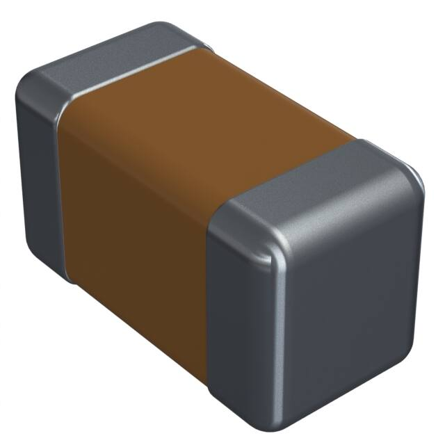
器件简介:AVX公司为满足汽车行业对组件机械强度增加的要求,开发了具有增强机械强度的MLCC,并命名为FLEXITERM®。这种结构设计用于提高标准陶瓷电容器的机械弯曲和温度循环性能。
引脚分配:文档中未提及具体的引脚分配信息。
参数特性:FLEXITERM®的主要特性包括高机械性能(可承受5mm弯曲测试保证)、增加的温度循环性能(超过3000次循环)、灵活的终止系统、减少电路板弯曲故障、基础金属电极系统、提供汽车级或商业级产品、AECQ200认证、符合VW 80808规范。
功能详解:FLEXITERM®设计用于在受到外部力作用时保持电气完整性,提供了比行业标准2mm更大的弯曲能力(高达5mm),超过5mm时电容器通常会失效。
应用信息:适用于高弯曲应力电路板、温度变化应用和汽车应用,以提高可靠性和机械性能。
封装信息:提供了多种尺寸的封装信息,包括0603、0805、1206、1210、1812和2220等,以及与封装相关的电压、电容、电容公差和包装方式的详细说明。