0
登录后你可以
  • 下载海量资料
  • 学习在线课程
  • 观看技术视频
  • 写文章/发帖/加入社区
会员中心
创作中心
发布
  • 发文章

  • 发资料

  • 发帖

  • 提问

  • 发视频

创作活动
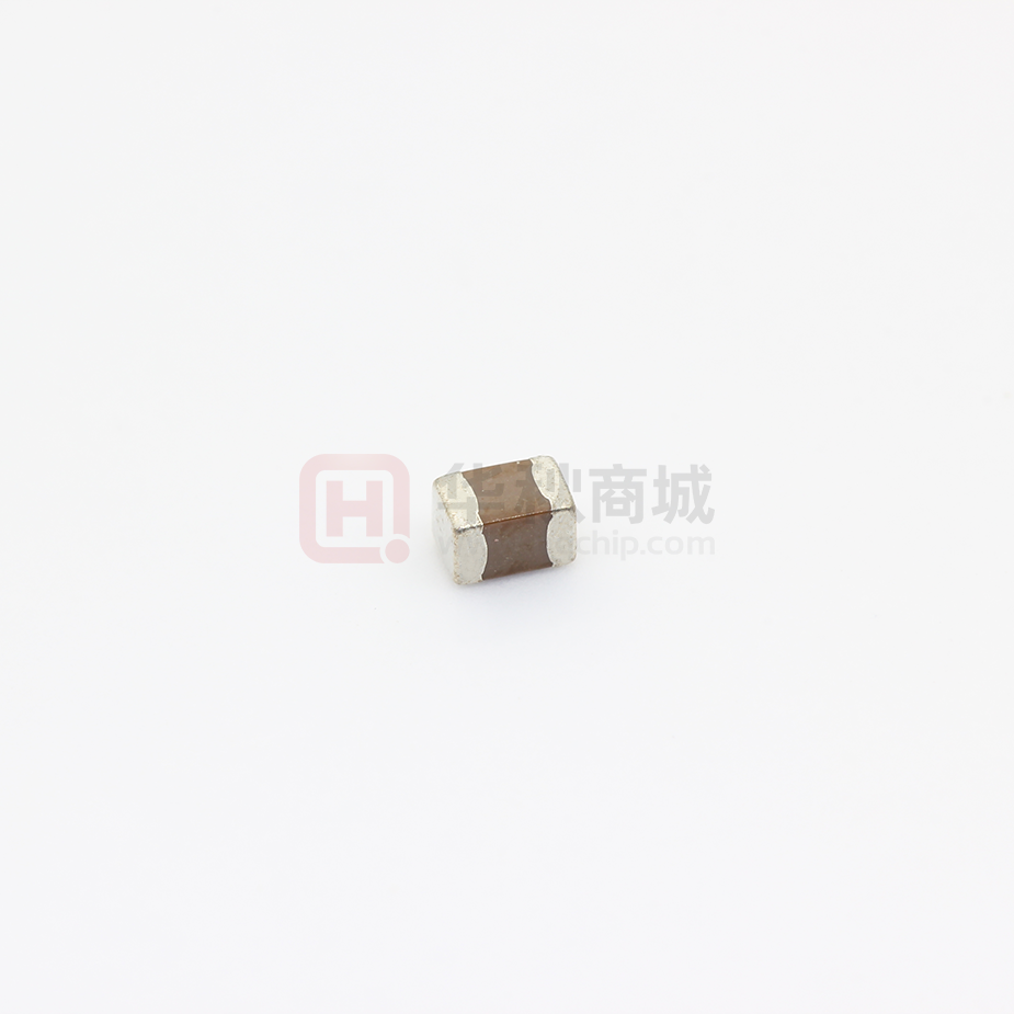
08053C224KAT2A

08053C224KAT2A

  • 厂商:

    AVX(艾维克斯)

  • 封装:

    0805

  • 描述:

    贴片电容(MLCC) 0805 220nF ±10% 25V X7R

  • 详情介绍
  • 数据手册
  • 价格&库存
08053C224KAT2A 数据手册
X7R Dielectric General Specifications X7R formulations are called “temperature stable” ceramics and fall into EIA Class II materials. X7R is the most popular of these intermediate dielectric constant materials. Its temperature variation of capacitance is within ±15% from -55°C to +125°C. This capacitance change is non-linear. Capacitance for X7R varies under the influence of electrical operating con-ditions such as voltage and frequency. X7R dielectric chip usage covers the broad spectrum of industrial applications where known changes in capacitance due to applied voltages are acceptable. PART NUMBER (SEE PAGE 4 FOR COMPLETE PART NUMBER EXPLANATION) 0805 5 С 103 M A T 2 A Size (L” x W”) Voltage 4V = 4 6.3V = 6 10V = Z 16V = Y 25V = 3 50V = 5 100V = 1 200V = 2 500V = 7 Dielectric X7R = C Capacitance Code (In pF) 2 Sig. Digits + Number of Zeros Capacitance Tolerance J = ± 5%* K = ±10% M = ± 20% Failure Rate A = Not Applicable Terminations T = Plated Ni and Sn Z= FLEXITERM®** Packaging 2 = 7” Reel 4 = 13” Reel *Optional termination Contact Factory For Multiples Special Code A = Std. Product *≤1μF only, contact factory for additional values **See FLEXITERM® X7R section NOTE: Contact factory for availability of Termination and Tolerance Options for Specific Part Numbers. Contact factory for non-specified capacitance values. 18 The Important Information/Disclaimer is incorporated in these specifications by reference and should be reviewed in full before placing any order. 100819 X7R Dielectric Specifications and Test Methods Parameter/Test Operating Temperature Range Capacitance Dissipation Factor Insulation Resistance Dielectric Strength Resistance to Flexure Stresses Appearance Capacitance Variation Dissipation Factor Insulation Resistance Solderability Resistance to Solder Heat Thermal Shock Load Life Appearance Capacitance Variation Dissipation Factor No breakdown or visual defects Charge device with 250% of rated voltage for 1-5 seconds, w/charge and discharge current limited to 50 mA (max) Note: Charge device with 150% of rated voltage for 500V devices. No defects ≤ ±12% Meets Initial Values (As Above) ≥ 95% of each terminal should be covered with fresh solder No defects, 10µF, 0.5Vrm @ 120Hz Charge device with rated voltage for 120 ± 5 secs @ room temp/humidity Meets Initial Values (As Above) Appearance Capacitance Variation Dissipation Factor Insulation Resistance Dielectric Strength Appearance Capacitance Variation Dissipation Factor Insulation Resistance Measuring Conditions Temperature Cycle Chamber 100,000MΩ or 1000MΩ - µF, whichever is less Insulation Resistance Dielectric Strength Load Humidity X7R Specification Limits -55ºC to +125ºC Within specified tolerance ≤ 10% for ≥ 50V DC rating≤ 12.5% for 25V DC rating ≤ 12.5% for 25V and 16V DC rating ≤ 12.5% for ≤ 10V DC rating Contact Factory for DF by PN No visual defects Dip device in eutectic solder at 260ºC for 60 seconds. Store at room temperature for 24 ± 2hours before measuring electrical properties. Step 1: -55ºC ± 2º 30 ± 3 minutes ≤ ±7.5% Step 2: Room Temp ≤ 3 minutes Meets Initial Values (As Above) Step 3: +125ºC ± 2º 30 ± 3 minutes Meets Initial Values (As Above) Step 4: Room Temp ≤ 3 minutes Meets Initial Values (As Above) No visual defects ≤ ±12.5% ≤ Initial Value x 2.0 (See Above) Repeat for 5 cycles and measure after 24 ± 2 hours at room temperature Charge device with 1.5 rated voltage (≤ 10V) in test chamber set at 125ºC ± 2ºC for 1000 hours (+48, -0) ≥ Initial Value x 0.3 (See Above) If RV > 10V then Life Test voltage will be 2xRV but there are exceptions (please contact AVX for further details on exceptions) Meets Initial Values (As Above) Remove from test chamber and stabilize at room temperature for 24 ± 2 hours before measuring. No visual defects ≤ ±12.5% ≤ Initial Value x 2.0 (See Above) ≥ Initial Value x 0.3 (See Above) Meets Initial Values (As Above) Store in a test chamber set at 85ºC ± 2ºC/ 85% ± 5% relative humidity for 1000 hours (+48, -0) with rated voltage applied. Remove from chamber and stabilize at room temperature and humidity for 24 ± 2 hours before measuring. The Important Information/Disclaimer is incorporated in these specifications by reference and should be reviewed in full before placing any order. 121219 19 X7R Dielectric Capacitance Range PREFERRED SIZES ARE SHADED SIZE 0101* 0201 0402 0603 0805 1206 Soldering Reflow Only Reflow Only Reflow/Wave Reflow/Wave Reflow/Wave Reflow/Wave Paper/Embossed Packaging (L) Length W) Width (t) Terminal Paper/Embossed All Paper All Paper All Paper Paper/Embossed mm 0.40 ± 0.02 0.60 ± 0.09 1.00 ± 0.10 1.60 ± 0.15 2.01 ± 0.20 3.20 ± 0.20 (in.) (0.016 ± 0.0008) (0.024 ± 0.004) (0.040 ± 0.004) (0.063 ± 0.006) (0.079 ± 0.008) (0.126 ± 0.008) mm 0.20 ± 0.02 0.30 ± 0.09 0.50 ± 0.10 0.81 ± 0.15 1.25 ± 0.20 1.60 ± 0.20 (in.) (0.008 ± 0.0008) (0.011 ± 0.004) (0.020 ± 0.004) (0.032 ± 0.006) (0.049 ± 0.008) (0.063 ± 0.008) mm 0.10± 0.04 0.15 ± 0.05 0.25 ± 0.15 0.35 ± 0.15 0.50 ± 0.25 0.50 ± 0.25 (in.) (0.004 ± 0.0016) (0.006 ± 0.002) (0.010 ± 0.006) (0.014 ± 0.006) (0.020 ± 0.010) (0.020 ± 0.010) WVDC 16 6.3 10 16 25 50 16 25 50 50 100 200 Cap 100 101 B A A A A A 6.3 10 C C C 6.3 10 16 25 G G G (pF) 150 151 B A A A A A C C C G G G 220 221 B A A A A A C C C G G G 330 331 B A A A A A C C C G G G 470 471 B A A A A A C C C G G 680 681 B A A A A C C C G 250 6.3 10 16 25 50 100 200 250 6.3 10 16 25 50 100 200 250 500 E E E E E E E J J J J J J G J J J J J J K G G J J J J J J K K 1000 102 B A A A A C C C C G G G G J J J J J J J 1500 152 B A A A A C C C C G G J G J J J J J J J 2200 222 B 3300 332 J J J J J J J K J M A A A A C C C C G G J G J J J J J J J J J J J J J J M A A A A C C C C G G J G J J J J J J J J J J J J J J M M 4700 472 A A A A C C C C G G J G J J J J J J J J J J J J J J 6800 682 A A A A C C C C G G J G J J J J J J J J J J J J J J P Cap 0.01 103 A A A A C C C C G G G J G J J J J J J J J J J J J J J P (μF) 0.015 153 C C C C G G G J J J J J J J N J J J J J M J Q 0.022 223 C C C C G G G J J J J J N N J J J J J M J Q 0.033 333 C C C C G G J J J J J N N N J J J J J M J Q 0.047 473 C C C C G G G J J J J J N N N J J J J J M M 0.068 683 C C C C M 0.1 104 C C C C 0.15 154 0.22 224 0.33 334 0.47 474 0.68 684 1.0 105 2.2 225 4.7 475 J 10 106 22 226 47 476 100 107 C C C C C C G G G J J J J J N N J J J J J P G G G G J J J J J N N J J J J P P P G G G G J J J J N N J J J J Q Q Q G G J J J J J N N N J J J J Q Q Q J J J J J N N N N N J J M P Q J J J J J N N N N N M M M P Q J J J N N N M M J J J N N N N M M J J J P P P P** Q Q Q Q Q** P P P Q Q Q Z P P X 200 250 J J P WVDC 16 SIZE 0101* 6.3 10 16 25 50 6.3 10 0201 16 25 50 6.3 10 16 0402 25 50 100 200 250 6.3 10 0603 16 25 50 100 200 250 Q Q X Q Q 6.3 10 16 25 0805 Letter A B C E G J K M N P Q X Y Z Max. Thickness 0.33 (0.013) 0.22 (0.009) 0.56 (0.022) 0.71 (0.028) 0.90 (0.035) 0.94 (0.037) 1.02 (0.040) 1.27 (0.050) 1.40 (0.055) 1.52 (0.060) 1.78 (0.070) 2.29 (0.090) 2.54 (0.100) 2.79 (0.110) PAPER EMBOSSED NOTE: Contact factory for non-specified capacitance values *EIA 01005 **Contact Factory for Specifications 20 The Important Information/Disclaimer is incorporated in these specifications by reference and should be reviewed in full before placing any order. 110819 50 100 1206 500 X7R Dielectric Capacitance Range PREFERRED SIZES ARE SHADED SIZE 1210 1812 1825 2220 2225 Soldering Reflow Only Reflow Only Reflow Only Reflow Only Reflow Only Packaging Paper/Embossed All Embossed All Embossed All Embossed All Embossed mm (in.) mm 3.30 ± 0.4 (0.130± 0.016) 2.50 ± 0.30 4.50 ± 0.30 (0.177 ± 0.012) 3.20 ± 0.20 4.50 ± 0.30 (0.177 ± 0.012) 6.40 ± 0.40 5.70 ± 0.50 (0.224 ± 0.020) 5.00 ± 0.40 5.72 ± 0.25 (0.225 ± 0.010) 6.35 ± 0.25 (0.250 ± 0.010) (L) Length W) Width (t) Terminal (in.) (0.098 ± 0.012) (0.126 ± 0.008) (0.252 ± 0.016) (0.197 ± 0.016) mm 0.50 ± 0.25 0.61 ± 0.36 0.61 ± 0.36 0.64 ± 0.39 0.64 ± 0.39 (in.) (0.020 ± 0.010) (0.024 ± 0.014) (0.024 ± 0.014) (0.025 ± 0.015) (0.025 ± 0.015) WVDC Cap 100 101 (pF) 150 151 220 221 330 331 470 471 680 681 1000 102 10 16 25 50 100 200 500 1500 152 J J J J J J M 2200 222 J J J J J J M 3300 332 J J J J J J M 4700 472 J J J J J J M 16 25 50 100 200 500 50 100 200 25 50 100 200 500 50 100 200 6800 682 J J J J J J M Cap 0.01 103 J J J J J J M K K K K K M M M X X X X M P P (μF) 0.015 153 J J J J J J P K K K K M M M M X X X X M P P 0.022 223 J J J J J J Q K K K K P M M M X X X X M P P 0.033 333 J J J J J J Q K K K K X M M M X X X X M P P P 0.047 473 J J J J J J Q K K K K X M M M X X X X M P 0.058 683 J J J J J M Q K K K K X M M M X X X X M P P 0.1 104 J J J J J M X K K K K X M M M X X X X M P P 0.15 154 J J J J M Z K K K P Z M M M X X X X M P X 0.22 224 J J J J P Z K K K P Z M M M X X X X M P X 0.33 334 J J J J Q K K M X Z M M X X X X M P X 0.47 474 M M M M Q K K P X Z M M X X X X M P X 0.68 684 M M P X X M M Q M P X X M P X M P 1.0 105 N N P X Z M M X 1.5 155 N N Z Z Z Z Z Z 2.2 225 X X Z Z Z Z Z 3.3 335 X X Z Z Z Z Z Z Z Z 4.7 475 Z Z Z Z 10 106 Z Z Z Z 22 226 Z Z Z 47 476 Z 100 107 16 25 WVDC 10 SIZE Z X X M P X X X M X Z Z X X M X Z Z X Z Z Z Z Z 100 200 Q Z Z 50 100 200 500 16 25 1210 50 100 200 500 50 1812 100 200 25 50 1825 100 2220 Letter A B C E G J K M N P Q X Y Z Max. Thickness 0.33 (0.013) 0.22 (0.009) 0.56 (0.022) 0.71 (0.028) 0.90 (0.035) 0.94 (0.037) 1.02 (0.040) 1.27 (0.050) 1.40 (0.055) 1.52 (0.060) 1.78 (0.070) 2.29 (0.090) 2.54 (0.100) 2.79 (0.110) PAPER 200 500 50 2225 EMBOSSED NOTE: Contact factory for non-specified capacitance values The Important Information/Disclaimer is incorporated in these specifications by reference and should be reviewed in full before placing any order. 011320 21
08053C224KAT2A
1. 物料型号:文档中提到了多种物料型号,例如“0805”、“1206”等,这些通常指的是电容器的尺寸。

2. 器件简介:X7R电介质是一种被称为“温度稳定”的陶瓷材料,属于EIA Class II材料。X7R是最受欢迎的中等介电常数材料之一,其电容值在-55°C至+125°C范围内的变化在±15%以内,这种变化是非线性的。

3. 引脚分配:文档中提到了不同的封装类型,如“0805”、“1206”等,并给出了引脚的宽度和间距,例如“0.10 0.04mm”等。

4. 参数特性:文档详细列出了X7R电介质的规格和测试方法,包括工作温度范围、电容公差、耗散因子、绝缘电阻、耐电压、耐弯应力、电容变化、焊接性和耐热性等。

5. 功能详解:X7R电介质芯片广泛应用于工业领域,适用于已知电容变化的场合。例如,电容值会因电压和频率等电气工作条件的影响而变化。

6. 应用信息:文档中没有提供具体的应用案例,但通常X7R电容器可用于滤波、旁路、能量存储等电路中。

7. 封装信息:文档列出了不同尺寸的封装信息,包括长度、宽度和最大厚度等。
08053C224KAT2A 价格&库存

很抱歉,暂时无法提供与“08053C224KAT2A”相匹配的价格&库存,您可以联系我们找货

免费人工找货
08053C224KAT2A
  •  国内价格
  • 50+3.41223
  • 500+3.07101
  • 5000+2.84353
  • 10000+2.72979
  • 30000+2.61605
  • 50000+2.54780

库存:0

08053C224KAT2A
    •  国内价格
    • 2000+0.14420

    库存:10000