Thin-Film RF/Microwave Directional Couplers
CP0302/CP0402/CP0603/CP0805 and DB0603N/DB0805 3dB 90°
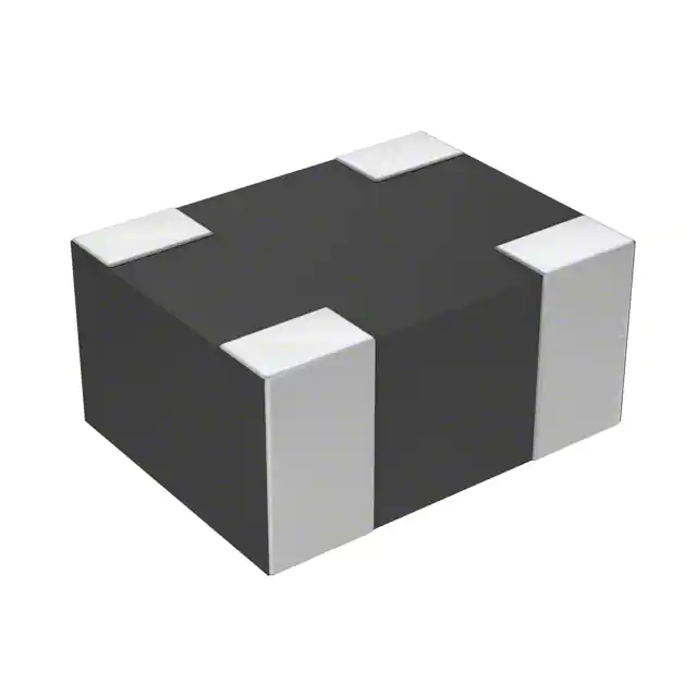
CP0805 SMD Type
GENERAL DESCRIPTION
ITF (INTEGRATED THIN-FILM) TECHNOLOGY
DIMENSIONS:�
millimeters (inches)
(Top View)
The ITF SMD Coupler is based on thin-film multilayer technology. The technology
provides a miniature part with excellent high frequency performance and rugged
construction for reliable automatic assembly.
The ITF Coupler is offered in a variety of frequency bands compatible with various types
of high frequency wireless systems.
FEATURES
•
•
•
•
•
•
•
•
APPLICATIONS
Small Size: 0805
Frequency Range: 800MHz - 3GHz
Characteristic Impedance: 50Ω
Operating / Storage Temp.:
-40°C to +85°C
Power Rating: 3W Continuous
Low Profile
Rugged Construction
Taped and Reeled
•
•
•
•
•
Mobile Communications
Satellite TV Receivers
GPS
Vehicle Location Systems
Wireless LAN’s
0805
L
2.03±0.1 (0.080±0.004)
W
1.55±0.1 (0.061±0.004)
T
0.98±0.1 (0.039±0.004)
A
0.56±0.25 (0.022±0.010)
B
0.35±0.15 (0.014±0.006)
HOW TO ORDER
CP
0805
Style
Size
Directional Coupler
0805
A
0902
A
Layout Type
Frequency
Sub-Type
(see layout types)
(see layout
sub-types)
MHz
Not RoHS Compliant
S
TR
Termination Code
W = Nickel/Solder
(Sn/Pb)
**S = Nickel / Lead
Free Solder
(Sn100)
Packaging Code
TR = Tape and Reel
**RoHS compliant
LEAD-FREE COMPATIBLE
COMPONENT
For RoHS compliant products,
please select correct termination style.
QUALITY INSPECTION
Finished parts are 100% tested for electrical parameters and visual
characteristics. Each production lot is evaluated on a sample basis for:
Recommended Pad Layout Dimensions mm (inches)
• Static Humidity: 85°C, 85% RH, 160 hours
• Endurance: 125°C, IR, 4 hours
TERMINATION
Nickel/Solder coating (Sn, Pb) compatible with automatic soldering
technologies: reflow, wave soldering, vapor phase and manual.
NOTE: Components must be mounted on the board with the white (Alumina) side
DOWN.
76
The Important Information/Disclaimer is incorporated in the catalog where these specifications came from or
available online at www.avx.com/disclaimer/ by reference and should be reviewed in full before placing any order.
012419
– rf microwave products –
�Thin-Film RF/Microwave Directional Couplers
CP0302/CP0402/CP0603/CP0805 and DB0603N/DB0805 3dB 90°
CP0805 Layout Types
I. Loss
-10
Coupling
-15
-20
0
-10
-30
Isolation
-35
-1
-2
Coupling
-15
R. Loss
-25
0
I. Loss
-5
dB
dB
-1
Type: A
Sub-Type: B
-20
-3
-4
Isolation
-25
-30
-5
-6
R. Loss
-35
-7
-40
-40
-8
-45
-50
0.60
-45
-50
0.60
-9
0.80
1.00
1.20
1.60
1.40
1.80
2.00
0.80
1.20
1.40
1.60
1.80
-10
2.00
Frequency (GHz)
Frequency (GHz)
Frequency
Band [MHz]
Coupling [dB]
CP0805A0836AS
824 - 849
16.5±1
CP0805A0881AS
CP0805A0902AS
CP0805A0947AS
CP0805A0897AS
CP0805A0942AS
CP0805A1441AS
CP0805A1747AS
CP0805A1842AS
CP0805A1880AS
CP0805A1960AS
CP0805A1907AS
CP0805A1890AS
869 - 894
890 - 915
935 - 960
880 - 915
925 - 960
1429 - 1453
1710 - 1785
1805 - 1880
1850 - 1910
1930 - 1990
1895 - 1920
1880 - 1900
16±1
16±1
15.5±1
16±1
15.5±1
12±1
10.5±1
10±1
9.5±1
9.5±1
9.5±1
9.5±1
P/N Examples
1.00
I. Loss (dB)
0
0
-5
I. Loss (dB)
Type: A
Sub-Type: A
VSWR
max
P/N
Examples
0.25
1.2
CP0805A0836BS
824 - 849
19±1
0.25
1.2
0.25
0.25
0.25
0.25
0.25
0.5
0.7
0.8
0.8
0.8
0.8
0.8
1.2
1.2
1.2
1.2
1.2
1.3
1.4
1.4
1.4
1.4
1.4
1.4
CP0805A0881BS
CP0805A0902BS
CP0805A0947BS
CP0805A0897BS
CP0805A0942BS
CP0805A1441BS
CP0805A1747BS
CP0805A1842BS
CP0805A1880BS
CP0805A1960BS
CP0805A1907BS
CP0805A1890BS
CP0805A2442BS
869 - 894
890 - 915
935 - 960
880 - 915
925 - 960
1429 - 1453
1710 - 1785
1805 - 1880
1850 - 1910
1930 - 1990
1895 - 1920
1880 - 1900
2400 - 2484
18.5±1
18±1
18±1
18.5±1
18±1
14.5±1
12.5±1
12.5±1
12±1
11.5±1
12±1
12±1
10±1
0.25
0.25
0.25
0.25
0.25
0.35
0.5
0.5
0.6
0.7
0.6
0.6
0.9
1.2
1.2
1.2
1.2
1.2
1.2
1.4
1.4
1.4
1.4
1.4
1.4
1.4
P/N
Examples
Frequency
Band [MHz]
Coupling
[dB]
I. Loss
max
VSWR
max
I. Loss
max
Frequency
Band [MHz]
Coupling
[dB]
I. Loss
max
VSWR
max
Type: A
Sub-Type: C
0
-5
-10
dB
-15
-20
-25
-30
I. Loss
Coupling
Isolation
R. Loss
CP0805A0836CS
824 - 849
14±1
0.5
1.4
CP0805A0881CS
869 - 894
13.5±1
0.5
1.4
CP0805A0902CS
890 - 915
13.5±1
0.5
1.4
CP0805A0947CS
935 - 960
13±1
0.5
1.4
1.4
-35
CP0805A0897CS
880 - 915
13.5±1
0.5
CP0805A0942CS
925 - 960
13±1
0.5
1.4
-40
CP0805A1441CS
1429 - 1453
9.5±1
1.15
1.8
-45
-50
0.60
CP0805A1747CS
CP0805A1842CS
CP0805A1880CS
Cp0805A1960CS
CP0805A1907CS
CP0805A1890CS
CP0805A2442CS
1710 - 1785
1805 - 1880
1850 - 1910
1930 - 1990
1895 - 1920
1880 - 1900
2400 - 2484
8±1
8±1
7.5±1
7.5±1
7.5±1
7.5±1
6±1
1.6
1.6
1.75
1.75
1.75
1.75
2.5
2.2
2.2
2.2
2.2
2.2
2.2
2.2
0.80
1.00
1.20
1.40
1.60
1.80
2.00
2.20
2.40
Frequency (GHz)
Important: Couplers can be used at any frequency within the indicated range.
The Important Information/Disclaimer is incorporated in the catalog where these specifications came from or
available online at www.avx.com/disclaimer/ by reference and should be reviewed in full before placing any order.
012419
– rf microwave products –
77
�Thin-Film RF/Microwave Directional Couplers
CP0302/CP0402/CP0603/CP0805 and DB0603N/DB0805 3dB 90°
CP0805 Layout Types
Type: A
Sub-Type: D
Type: A
Sub-Type: E
0
Coupling
-15
-10
-25
-30
dB
Isolation
-20
I. Loss
-5
R. Loss
-15
-20
-35
Coupling
Isolation
-40
-25
-45
-50
0.60
-30
0.50
0.80
1.00
1.20
1.40
1.60
1.80
2.00
2.20
2.40
R. Loss
0.75
Frequency
Band [MHz]
1.00
1.25
1.50
1.75
2.00
Coupling
[dB]
I. Loss
max
VSWR
max
Frequency (GHz)
Frequency (GHz)
P/N
Examples
I. Loss (dB)
-10
dB
0
I. Loss
-5
Coupling [dB]
I. Loss
max
VSWR
max
P/N
Examples
Frequency
Band [MHz]
CP0805A0836ES
824 - 849
11±1
0.85
1.4
CP0805A0881ES
869 - 894
10.5±1
0.85
1.4
CP0805A0902ES
890 - 915
10.5±1
0.85
1.4
CP0805A0836DS
824 - 849
13.0±1
0.5
1.4
CP0805A0881DS
869 - 894
12.5±1
0.5
1.4
CP0805A0902DS
890 - 915
12.5±1
0.5
1.4
CP0805A0947DS
CP0805A0897DS
CP0805A0942DS
CP0805A1441DS
CP0805A1747DS
CP0805A1842DS
CP0805A1880DS
Cp0805A1960DS
CP0805A1907DS
935 - 960
880 - 915
925 - 960
1429 - 1453
1710 - 1785
1805 - 1880
1850 - 1910
1930 - 1990
1895 - 1920
12±1
12.5±1
12±1
8.5±1
7±1
7±1
7±1
6.5±1
6.5±1
0.5
0.5
0.5
1.25
1.85
1.85
1.85
2.15
2.15
1.4
1.4
1.4
1.8
1.8
1.8
1.8
2.1
2.1
CP0805A0947ES
935 - 960
10±1
0.85
1.4
CP0805A0897ES
880 - 915
10.5±1
0.85
1.4
CP0805A0942ES
925 - 960
10±1
0.85
1.4
CP0805A1441ES
CP0805A1747ES
CP0805A1842ES
1429 - 1453
1710 - 1785
1805 - 1880
7±1
5.5±1
5.5±1
1.8
2.7
2.7
1.8
2.2
2.2
CP0805A1880ES
1850 - 1910
5±1
3.15
2.4
Cp0805A1960ES
1930 - 1990
5±1
3.15
2.4
CP0805A1907ES
1895 - 1920
5±1
3.15
2.4
CP0805A1890DS
1880 - 1900
7±1
1.85
1.8
CP0805A1890ES
1880 - 1900
5±1
3.15
2.4
CP0805A2442DS
2400 - 2484
5.5±1
2.4
2.1
CP0805A2442ES
2400 - 2484
4±1
4.2
2.4
Important: Couplers can be used at any frequency within the indicated range.
78
The Important Information/Disclaimer is incorporated in the catalog where these specifications came from or
available online at www.avx.com/disclaimer/ by reference and should be reviewed in full before placing any order.
081320
– rf microwave products –
�Thin-Film RF/Microwave Directional Couplers
CP0302/CP0402/CP0603/CP0805 and DB0603N/DB0805 3dB 90°
CP0805 Layout Types
Type: B
Sub-Type: B
-3
-4
-5
-25
-30
R. Loss
-35
-40
Isolation
-6
-7
-8
1.40
1.60
1.80
2.00
2.20
2.40
-1
-2
-10
-15
-20
-25
-30
-35
-40
-9
1.20
0
I. Loss
-3
Coupling
-4
-5
R. Loss
-6
-7
Isolation
-8
-9
-45
-10
2.60
-50
1.10
Frequency (GHz)
I. Loss (dB)
-1
-2
Coupling
-45
-50
1.00
-5
dB
dB
-15
-20
0
0
I. Loss
I. Loss (dB)
0
-5
-10
Type: B
Sub-Type: C
1.30
1.50
1.70
2.10
1.90
2.30
-10
2.50
Frequency (GHz)
P/N
Examples
Frequency
Band [MHz]
Coupling [dB]
I. Loss
max
VSWR
max
P/N
Examples
Frequency
Band [MHz]
Coupling
[dB]
I. Loss
max
VSWR
max
CP0805B0836BS
CP0805B0881BS
CP0805B0902BS
CP0805B0947BS
CP0805B0897BS
CP0805B0942BS
CP0805B1441BS
CP0805B1747BS
CP0805B1842BS
CP0805B1880BS
CP0805B1960BS
CP0805B1907BS
CP0805B1890BS
CP0805B2442BS
824 - 849
869 - 894
890 - 915
935 - 960
880 - 915
925 - 960
1429 - 1453
1710 - 1785
1805 - 1880
1850 - 1910
1930 - 1990
1895 - 1920
1880 - 1900
2400 - 2484
23.5±1
23±1
22.5±1
22±1
23±1
22±1
18.5±1
17±1
16.5±1
16.5±1
16±1
16±1
16±1
14±1
0.25
0.25
0.25
0.25
0.25
0.25
0.25
0.25
0.25
0.25
0.25
0.25
0.25
0.4
1.2
1.2
1.2
1.2
1.2
1.2
1.2
1.2
1.2
1.2
1.2
1.2
1.2
1.2
CP0805B0836CS
CP0805B0881CS
CP0805B0902CS
CP0805B0947CS
CP0805B0897CS
CP0805B0942CS
CP0805B1441CS
CP0805B1747CS
Cp0805B1842CS
CP0805B1880CS
Cp0805B1960CS
CP0805B1907CS
CP0805B1890CS
CP0805B2442CS
824 - 849
869 - 894
890 - 915
935 - 960
880 - 915
925 - 960
1429 - 1453
1710 - 1785
1805 - 1880
1850 - 1910
1930 - 1990
1895 - 1920
1880 - 1900
2400 - 2484
25±1
24.5±1
24±1
24±1
24.5±1
24±1
20±1
18.5±1
18.5±1
18±1
17.5±1
18±1
18±1
16±1
0.25
0.25
0.25
0.25
0.25
0.25
0.25
0.25
0.25
0.25
0.25
0.25
0.25
0.4
1.2
1.2
1.2
1.2
1.2
1.2
1.2
1.2
1.2
1.2
1.2
1.2
1.2
1.2
Type: B
Sub-Type: B
0
0
I. Loss
-5
dB
-15
-20
-25
-30
-35
-40
-1
-2
Coupling
-3
-4
R. Loss
-5
-6
Isolation
-45
-50
1.00
I. Loss (dB)
-10
-7
-8
1.20
1.40
1.60
1.80
2.00
2.20
-9
-10
2.40
Frequency (GHz)
Important: Couplers can be used at any frequency within the indicated range.
P/N Examples
Frequency Band [MHz]
CP0805B0836AS
CP0805B0881AS
CP0805B0902AS
CP0805B0947AS
CP0805B0897AS
824 - 849
869 - 894
890 - 915
935 - 960
880 - 915
Coupling [dB] I. Loss max
21.5±1
21±1
21±1
20.5±1
21±1
0.25
0.25
0.25
0.25
0.25
VSWR max
1.2
1.2
1.2
1.2
1.2
CP0805B0942AS
925 - 960
20.5±1
0.25
1.2
CP0805B1441AS
CP0805B1747AS
Cp0805B1842AS
CP0805B1880AS
CP0805B1960AS
1429 - 1453
1710 - 1785
1805 - 1880
1850 - 1910
1930 - 1990
17±1
15.5±1
15.5±1
15±1
14.5±1
0.25
0.25
0.3
0.3
0.4
1.2
1.2
1.2
1.2
1.2
CP0805B1907AS
1895 - 1920
15±1
0.3
1.2
CP0805B1890AS
CP0805B2442AS
1880 - 1900
2400 - 2484
15±1
13±1
0.3
0.4
1.2
1.2
The Important Information/Disclaimer is incorporated in the catalog where these specifications came from or
available online at www.avx.com/disclaimer/ by reference and should be reviewed in full before placing any order.
082420
– rf microwave products –
79
�Thin-Film RF/Microwave Directional Couplers
CP0302/CP0402/CP0603/CP0805 and DB0603N/DB0805 3dB 90°
CP0805 Layout Types
VHF DIRECTIONAL COUPLER
UHF DIRECTIONAL COUPLER
CP0805L0155ASTR
CP0805L0436BSTR
COUP
50
OHM
IN
P/N
Frequency
[MHz]
Coupling
[dB]
R. Loss
[dB]
I. Loss max
[dB]
Directivity
[dB]
CP0805L0155ASTR
155
17.1±1
24
0.35
22
dB
Coupling
[dB]
R. Loss
[dB]
I. Loss max
[dB]
Directivity
[dB]
CP0805L0436BSTR
403-470
15.85±1
35
0.25
22
0
-8
-12
R. Loss
-40
-50
100
200
300
400
500
-1
Coupling
-20
-2
-30
-40
-16
Isolation
0
I. Loss
-10
-4
Coupling
-20
-30
Frequency
[MHz]
dB
-10
P/N
0
I. Loss
I. Loss (dB)
0
-50
-3
Isolation
-4
R. Loss
-60
200
-20
600
300
-5
400
500
600
Frequency (MHz)
Frequency (MHz)
Important: Couplers can be used at any frequency within the indicated range.
80
OUT
The Important Information/Disclaimer is incorporated in the catalog where these specifications came from or
available online at www.avx.com/disclaimer/ by reference and should be reviewed in full before placing any order.
012419
– rf microwave products –
700
-6
800
I. Loss (dB)
OUT
50
OHM
COUP
E
A
IN
�Thin-Film RF/Microwave Directional Couplers
CP0302/CP0402/CP0603/CP0805 and DB0603N/DB0805 3dB 90°
CP0805 and CP0603 Test Jig
ITF TEST JIG FOR COUPLER TYPES 0805 AND 0603 SMD
GENERAL DESCRIPTION
MEASUREMENT PROCEDURE
This jig is designed for the testing of CP0805 and CP0603 series
Directional Couplers using a vector network analyzer.
When measuring a component, it can be either soldered or pressed by
a non-metallic stick until all four ports touch the appropriate pads. To
measure the coupling (and the R. Loss) place the component on the Port
1 & Port 2 pads. Use two SMA 50Ω terminations (male) to terminate the
ports, which are not connected to the network analyzer, and connect the
network analyzer to the two ports. A 90° rotation of the component on its
pads allows measuring a second parameter (I. Loss).
It consists of a FR4 multi-layer substrate, having 50Ω microstrips as
conducting lines and a ground plane in the middle layer, located at a
distance of 0.2mm from the microstrips.
The connectors are SMA type (female), ‘Johnson Components Inc.’ Product
P/N: 142-0701-881.
The jig is designed for a full 2-port calibration. LOAD calibration can be
done either by a 50Ω SMA termination, or by soldering a 50Ω chip resistor
at the 50Ω ports.
Connector (1 of 12)
P/N 142-0701-881
Load & Thru
Calibration Area
Short
Open
Port 1
Port 2
Coupler 0805
50
50
Port 1
Port 2
Coupler 0603
50
50
CP0805 SERIES DIRECTIONAL COUPLERS
CP0805xxxxxxSTR (Sn100)
Orientation and Tape and Reel Packaging Specification
(Top View)
(Top View)
COUP
50
OHM
COUP
50
OHM
COUP
RF
IN
RF
OUT
RF
IN
RF
OUT
RF
IN
RF
OUT
RF
IN
TYPE AA
TYPE AB
TYPE AA
50
OHM
M
50
OHM
C
COUP
RF
OUT
TYPE AB
50
OHM
COUP
50
OHM
COUP
50
OHM
COUP
50
OHM
COUP
50
OHM
RF
IN
RF
OUT
RF
IN
RF
OUT
RF
IN
RF
OUT
RF
IN
RF
OUT
RF
IN
RF
OUT
RF
IN
RF
OUT
TYPE AE
TYPE AC
COUP
RF
IN
COUP
RF
IN
COUP
RF
OUT
50
OHM
RF
OUT
50
OHM
RF
OUT
50
OHM
TYPE BA
TYPE BB
RF
IN
COUP
RF
IN
COUP
RF
IN
COUP
RF
OUT
50
OHM
RF
OUT
50
OHM
RF
OUT
50
OHM
TYPE BC
TYPE BA
The parts should be mounted on the PCB with White (Alumina)side down
and the “dark” side up.
TYPE AE
TYPE BB
L
RF
IN
TYPE AD
V
TYPE AD
T
TYPE AC
K
COUP
F
50
OHM
Y
COUP
TYPE BC
The parts should be mounted on the PCB with printed side up.
The Important Information/Disclaimer is incorporated in the catalog where these specifications came from or
available online at www.avx.com/disclaimer/ by reference and should be reviewed in full before placing any order.
012419
– rf microwave products –
81
�
很抱歉,暂时无法提供与“CP0805A0881BWTR”相匹配的价格&库存,您可以联系我们找货
免费人工找货