Hybrid Couplers 3dB, 90º
Type PC2025A2100AT00
GENERAL DESCRIPTION
The PC2025A2100AT00 is a RoHS compliant low profile wideband 3dB hybrid
coupler which can support mobile applications, including PCS and DCS
applications. The power coupler series of components is based on AVX’s patented
MLO™ technology (US patents 6,987309, 7,068,124) which incorporates lumped
elements and micro vias. The resultant designs and finished structures allow for
the integration of high Q passives in a low cost high density interconnect
component. The PC2025A2100AT00 is a multifunctional component designed for
attenuators, phase shifters, LNAs, balance amplifiers and signal distribution. All
components are electrically tested prior to tape and reel. Reliability testing is
performed to JEDEC and Mil standards. Finishes are available in RoHS compliant
NiSn and immersion Au.
FEATURES
APPLICATIONS
• 1.5 – 2.1 GHz
• Excellent Isolation
• DCS and PCS
• Expansion Matched to PCB
• 90º Quadrature
• Surface Mountable
• RoHS Compliant
• Available in Tape and Reel
•
•
•
•
Mobile communications
GPS
Vehicle location systems
Wireless LAN’s
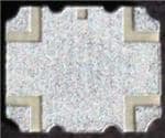
LAND GRID ARRAY
ADVANTAGES
•
•
•
•
TOP VIEW
Inherent Low Profile
Excellent Solderability
Low Parasitics
Better Heat Dissipation
mm (inches)
L
W
T
HOW TO ORDER
PC
2025
A
2100
A
T
00
1
Series
Size
Type
Frequency
(MHz)
Standard
Testing
Termination
7 = Au
T = NiSn
Product
Code
00 = Standard
Product
Packaging
Code
1 = Bulk
2 = 500 pcs, 7" reel
4 = 2000 pcs, 13" reel
6.35 (0.25)
5.08 (0.20)
1.0 (0.04)
ELECTRICAL SPECIFICATIONS*
Frequency
(GHz)
Isolation
(dB min)
I. L.
(dB max)
VSWR
1.5 – 2.1
18
0.25
1.25
Amplitude
Balance
(dB max)
±0.45
Phase
Balance
(Degrees)
±3º
Max Power
(Watts)
30
Operating
Temperature
(ºC)
-55 to +85
* Specification based on performance of component assembled properly on printed circuit board with 50Ω nominal impedance.
QUALITY INSPECTION
TERMINATION
Finished parts are 100% tested for electrical
parameters and visual characteristics.
Finishes include NiSn, and immersion Au. All
finishes compatible with automatic soldering
technologies: Pb free reflow, wave soldering, vapor
phase and manual.
OPERATING
TEMPERATURE
- 55ºC to +85ºC
1
�Hybrid Couplers 3dB, 90º
Type PC2025A2100AT00
MECHANICAL OUTLINE
TOP VIEW
(Near-side)
BOTTOM VIEW
(Far-side)
6.35 ± 0.25
(0.250 ± 0.010)
0.46 ±0.10
(0.018 ± 0.004)
Pin 1
3.56 ± 0.10
(0.140 ± 0.004)
Pin 2
Pin 2
5.08 ± 0.25
(0.200 ± 0.010)
Pin 4
Pin 1
3.08 ± 0.10
(0.123 ± 0.004)
Pin 3
Pin 3
Pin 4
4.35 ± 0.10
(0.172 ± 0.004)
SIDE VIEW
1.00 ± 0.27
(0.039 ± 0.011)
Dimensions mm (inches)
Tolerances are Non-Cumulative
2
1.0 ±0.10
(0.040 ± 0.004)
�Hybrid Couplers 3dB, 90º
Type PC2025A2100AT00
TYPICAL PERFORMANCE: 1.5 TO 2.1 GHZ
Insertion Loss
Coupling
Amplitude Balance
Phase Balance
Return Loss
Isolation
3
�Hybrid Couplers 3dB, 90º
Type PC2025A2100AT00
HYBRID COUPLER TEST JIGS
GENERAL DESCRIPTION
These jigs are designed for testing the 3dB Hybrid Couplers
using a Vector Network Analyzer. They consist of a dielectric
substrate, having Cu microstrips as conducting lines and a
bottom ground plane located at a distance of 0.254mm from
the microstrips.
The substrate used is Taconic RF 35 0100. The connectors
are SMA type (female), ‘Johnson Components Inc.’ Product
PIN: l42-070l-84l. Both a measurement jig and a calibration
jig are provided. The calibration jig is designed for a full 2port calibration, and consists of an open line, short line and
through line. LOAD calibration can be done by a 502 SMA
termination.
MOUNTING AND MEASUREMENT PROCEDURE
PIN CONFIGURATION
MLO™ hybrid couplers require a 50Ω transmission lines
leading to and from all of the RF ports. Proper grounding is
required in order to ensure optimal device performance.
All of the MLO™ components utilize castellated interconnects which allow for high yield assembly, expansion
matched and halogen free dielectrics.
The MLO™ hybrid coupler is a symmetrical device. When a
port is designated as the input, automatically the two output
and isolated ports are defined. For example, if the input port
for a device was selected to be Pin 1, Pin 2 is automatically
the isolated port, Pin 4 is the 0 degree reference output
port, and Pin 3 is the output port which “lags” behind the
reference output port by 90 degrees. Similarly, if Pin 3 was
to be selected as the input port, the adjacent port on the
long side (Pin 4) is the isolated port, the adjacent port on
the short side (Pin 2) is the 0 degree output port, and the
opposite port (Pin 1) is the 90 degree output port.
The PC2025A2100 part has an orientation marker to denote
Pin 1. Once port one is determined the other ports are
As defined; See the chart below for clarification:
1
4
Configuration
Splitter
Splitter
Splitter
Splitter
*Combiner
*Combiner
*Combiner
*Combiner
2
3
Pin 1
Pin 2
Pin 3
Pin 4
Input
Isolated
-3dB ∠-90
-3dB ∠
Isolated
Input
-3dB ∠
-3dB ∠-90
-3dB ∠-90
-3dB ∠
Input
Isolated
-3dB ∠
-3dB ∠-90
Isolated
Input
A ∠-90
A ∠
Isolated
Output
A ∠
A ∠-90
Output
Isolated
Isolated
Output
A ∠-90
A ∠
Output
Isolated
A ∠
A ∠-90
*Note: “A” is the amplitude of the applied signals. When two quadrature signals
with equal amplitudes are applied to the coupler as described they will combine at
the output port.
MEASUREMENT PROCEDURE
Measurement Jig
Connector 1
Connector 2
Connector 4
Connector 3
4
Calibration Jig
�Hybrid Couplers 3dB, 90º
Type PC2025A2100AT00
AUTOMATED SMT ASSEMBLY
surface mount assembly of MLO TM RF devices onto the
PCB. Stencil thickness and aperture openings should be
adjusted according to the optimal solder volume. The
following are general recommendations for SMT mounting
of MLOTM devices onto the PCB.
The following section describes the guidelines for
automated SMT assembly of MLOTM RF devices which are
typically Land Grid Array (LGA) packages or side termination
SMT packages.
Control of solder and solder paste volume is critical for
SMT REFLOW PROFILE
and slower preheating time may be required to improve the
out-gassing of solder paste. In addition, the reflow profile
depends on the PCB density and the type of solder paste
used. Standard no-clean solder paste is generally
recommended. If another type of flux is used, complete
removal of flux residual may be necessary. Example of a
typical lead free reflow profile is shown below:
Common IR or convection reflow SMT processes shall be
used for the assembly. Standard SMT reflow profiles, for
eutectic and Pb free solders, can be used to surface mount
the MLO TM devices onto the PCB. In all cases, a
temperature gradient of 3°C/sec, or less, should be
maintained to prevent warpage of the package and to
ensure that all joints reflow properly. Additional soak time
tp
Tp
Critical Zone
TL to Tp
Ramp-up
Temperature
TL
tL
Ts max
Ts min
Ramp-down
ts
Preheat
25
t 25ºC to Peak
Time
Profile Parameter
Ramp-up rate (Tsmax to Tp)
Preheat temperature (Ts min to Ts max)
Preheat time (ts)
Time above TL, 217ºC (tL)
Peak temperature (Tp)
Time within 5ºC of peak temperature (tp)
Ramp-down rate
Time 25ºC to peak temperature
Pb free, Convection, IR/Convection
3ºC/second max.
150ºC to 200ºC
60 – 180 seconds
60 – 120 seconds
260°C
10 – 20 seconds
4ºC/second max.
6 minutes max.
5
�Hybrid Couplers 3dB, 90º
Type PC2025A2100AT00
RECOMMENDED PAD LAYOUT
To ensure proper electrical and thermal performance
there must be gound plane with 100%
solder connection underneath the part
PC2100
4.42 (0.174)
Multiple plated
thru holes
to ground
0.61 (0.024)
0.61
(0.024)
3.15
(0.124)
1.14 SQ
(0.045)
2.51
(0.099)
50Ω
Transmission
Line
Dimensions are in mm (inches)
6
�
很抱歉,暂时无法提供与“PC2025A2100AT002”相匹配的价格&库存,您可以联系我们找货
免费人工找货