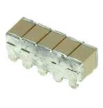
ST201C476MAJ10

ST201C476MAJ10

  • 厂商:

    AVX(艾维克斯)

  • 封装:

    CAP_27.3X7.62MM_SM

  • 描述:

    贴片电容(MLCC) CAP_27.3X7.62MM_SM 47µF ±20% 100V X7R

  • 详情介绍
  • 数据手册
  • 价格&库存
ST201C476MAJ10 数据手册
High-CV SMPS Capacitors TurboCap™ The TurboCapTM, MLC capacitors from AVX Corporation are characterized with very high capacitance in a small volume. By vertical stacking of the ceramic elements, the footprint required for mounting the capacitors is greatly reduced. TurboCapsTM are ideally suited as filters in the input and output stages of switch mode power supplies (SMPS). With their ultra-low ESR, these capacitors are designed to handle high ripple current at high frequencies and high power levels. The DIP leads in either thruhole or surface mount configurations offer superior stress relief to the ceramic elements. The leads effectively decouple the parts from the board and minimize thermally or mechanically induced stresses encountered during assembly, temperature cycling or other environmental conditions. TYPICAL APPLICATION OF TURBOCAPTM SMPS CAPACITORS FOR INPUT AND OUTPUT FILTERS IN DC/DC CONVERTERS SNUBBER Vout Vin OUTPUT FILTER INPUT FILTER VCC FB G PWM CONTROLLER GND Performance of SMPS capacitors can be simulated by downloading SpiCalci software program http://www.avx.com/download/software/SpiCalci-AVX.zip Custom values, ratings and configurations are also available. The Important Information/Disclaimer is incorporated in the catalog where these specifications came from or available online at www.avx.com/disclaimer/ by reference and should be reviewed in full before placing any order. 011419 – advanced ceramic capacitors – 53 High-CV SMPS Capacitors TurboCap™ ELECTRICAL SPECIFICATIONS Temperature Coefficient Temperature Coefficient ±15%, -55° to +125°C Capacitance Test (MIL-STD-202 Method 305) 25°C, 1.0±0.2 Vrms (open circuit voltage) at 1KHz Dielectric Withstanding Voltage 25°C (Flash Test) 250% rated voltage for 5 seconds with 50 mA max charging current. Dissipation Factor 25°C 2.5% Max @ 25°C, 1.0±0.2 Vrms (open circuit voltage) at 1KHz Moisture Resistance (MIL-STD-202 Method 106) Ten cycles with no voltage applied. Insulation Resistance 25°C (MIL-STD-202 Method 302) 500 MΩ-μF, whichever is less. Thermal Shock (MIL-STD-202 Method 107, Condition A) Life Test (1000 hrs) X7R: 150% rated voltage at +125°C. Immersion Cycling (MIL-STD-202 Method 104, Condition B) Insulation Resistance 125°C (MIL-STD-202 Method 302) 50 MΩ-μF, whichever is less. Resistance To Solder Heat (MIL-STD-202, Method 210, Condition B, for 20 seconds) Typical ESR Performance (Ω) ESR @ 10KHz ESR @ 50KHz ESR @ 100KHz 27μF 0.007 0.003 0.002 47μF 0.004 0.002 0.0015 100μF 0.003 0.0015 0.001 Not RoHS Compliant HOW TO ORDER 5 ST12 AVX Style ST12 ST20 AVX Styles: ST12 and ST20 Voltage 25V = 3 50V = 5 100V = 1 C Temperature Coefficient X7R = C 186 M Capacitance Code (2 significant digits + number of zeros) 1 μF = 105 10 μF = 106 100 μF = 107 A Capacitance Tolerance M = ±20% N Test Level A = Standard Termination N = Straight Lead J = Leads formed in L = Leads formed out CAPACITANCE (ΜF) ST12 ST20 Voltage Cap (μF) 50V 100V 25V 50V 100V .82 1.3 2.7 8.2 ...03 12 ...05 14 18 ...03 ...03 22 27 ...10 ...05 ...05 ...03 47 50 54 ...05 ...10 ...10 68 ...03 100 ...05 220 ...10 ...10 The Important Information/Disclaimer is incorporated in the catalog where these specifications came from or available online at www.avx.com/disclaimer/ by reference and should be reviewed in full before placing any order. 090518 – advanced ceramic capacitors – 03 Number of Leads Per Side 03 = 3 05 = 5 10 = 10 High-CV SMPS Capacitors TurboCap™ E D B A 1.397 (0.055) ±0.254 (0.010) 6.35 (0.25) MIN. 0.254 (0.010) TYP. 0.508 (0.020) TYP. C 3, 5 or 10 leads per side 2.54 (0.100) TYP. 2.54 (0.100) MAX. 0.635 (0.025) MIN. “N” STYLE LEADS E D B 0.254 (0.010) RAD. TYP. A 1.778 (0.070) ± 0.254 (0.010) 1.397 (0.055) ±0.254 (0.010) B 0.508 (0.020) TYP. 3, 5 or 10 leads per side 1.397 (0.055) ± 0.127 (0.005) C 2.54 (0.100) TYP. 2.54 (0.100) MAX. 0.635 (0.025) MIN. “J” STYLE LEADS E D B A 1.778 (0.070) ± 0.254 (0.010) 1.397 (0.055) ±0.254 (0.010) B 0.508 (0.020) TYP. 3, 5 or 10 leads per side C 0.254 (0.010) RAD. TYP. 1.397 (0.055) ± 0.127 (0.005) 2.54 (0.100) TYP. 2.54 (0.100) MAX. 0.635 (0.025) MIN. “L” STYLE LEADS DIMENSIONS millimeters (inches) Style A (max.) B (max.)* C ± 0.635 (± 0.025) D (max.) E (max.) Lead Style No. of Leads Per Side ST125C***M*N03 ST125C***M*N05 ST125C***M*N10 ST205C***M*N03 ST205C***M*N05 3.56 (0.140) 3.56 (0.140) 3.56 (0.140) 5.59 (0.220) 5.59 (0.220) 5.21 (0.205) 5.21 (0.205) 5.21 (0.205) 7.24 (0.285) 7.24 (0.285) 5.08 (0.200) 5.08 (0.200) 5.08 (0.200) 6.35 (0.250) 6.35 (0.250) 10.8 (0.425) 15.9 (0.625) 27.9 (1.100) 9.5(0.375) 14.6 (0.575) 6.35 (0.250) 6.35 (0.250) 6.35 (0.250) 7.62 (0.300) 7.62 (0.300) N N N N N 03 05 10 03 05 ST205C***M*N10 5.59 (0.220) 7.24 (0.285) 6.35 (0.250) 27.3 (1.075) 7.62 (0.300) N 10 *The “B” dimension is defined for the “N” Style leads. The “L” and “J” Style Leads are 0.381 (0.015) longer. The ST12 will be 5.89 (0.220), the ST20 will be 7.62 (0.300). The Important Information/Disclaimer is incorporated in the catalog where these specifications came from or available online at www.avx.com/disclaimer/ by reference and should be reviewed in full before placing any order. 011419 – advanced ceramic capacitors – 55
ST201C476MAJ10
物料型号:TurboCap™ MLC电容器

器件简介:这些电容器具有在小体积内非常高的电容,通过垂直堆叠陶瓷元件,大大减少了安装所需的占用空间。它们非常适合作为开关模式电源(SMPS)输入和输出阶段的滤波器。

引脚分配:DIP引脚可以是通孔或表面贴装配置,提供了优越的应力缓解给陶瓷元件。

参数特性:具有超低的等效串联电阻(ESR),设计用于在高频和高功率水平下处理高纹波电流。

功能详解:文档提供了电容器在DC/DC转换器输入和输出滤波器以及抑制器中的典型应用示例。

应用信息:电容器的性能可以通过下载SpiCalci软件程序进行模拟。

封装信息:提供了详细的尺寸信息和引脚样式选项,包括“N”(直引脚)、“J”(引脚形成内)和“L”(引脚形成外)。

此外,文档还包含了电气规格、订购指南、温度系数、电容测试、耗散因子、绝缘电阻、介质耐电压、寿命测试、耐湿性、热冲击和耐焊热性等参数。

ST201C476MAJ10 价格&库存

很抱歉,暂时无法提供与“ST201C476MAJ10”相匹配的价格&库存,您可以联系我们找货

免费人工找货
ST201C476MAJ10
  •  国内价格 香港价格
  • 1+499.705071+64.42163
  • 32+395.9814732+51.04965
  • 64+384.8215264+49.61092
  • 128+375.62806128+48.42571

库存:491