UltraThin Ceramic Capacitors
UT Series
The Ultrathin (UT) series of ceramic capacitors is a new product offering from AVX. The UT series was designed to meet the stringent thickness requirements of our customers. AVX developed a new termination process (FCT - Fine Copper Termination) that provides unbeatable flatness and repeatability. The series includes products < 0.35mm in height and is targeted for applications such as Smart cards, Memory modules, High Density SIM cards, Mobile phones, MP3 players, and embedded solutions.
HOW TO ORDER
UT 02 3 D 103 M A T 2 D
Style Ultra Thin
Case Size 0402
Rated Voltage 6 = 6.3V Z = 10V Y = 16V 3 = 25V
Temperature Characteristic X5R
Coded Cap (in pF) 2 Significant Digits + Number of Zeros
Cap Tolerance ± 20%
Termination Style Commercial
Termination T = 100% Sn C = Cu
Packaging 2 = 7" Reel 15,000 pcs 4 = 13" Reel 50,000 pcs
Thickness D = 0.30mm max E = 0.25mm max F = 0.15mm max (only availabe in Cu Termination)
RECOMMENDED SOLDER PAD DIMENSIONS (Sn Termination)
L BL W BL End View T Side View L Top View
0.50 (0.020)
mm (inches)
0.50 (0.020)
0.60 (0.024)
TYPICAL Cu THICKNESS
µM mil TT 10.0 ± 4.00 0.40 ± 0.16 TT
1.70 (0.067)
PART DIMENSIONS
Thickness D E F L 1.00 ± 0.10 (0.039±0.004) 1.00 ± 0.10 (0.039±0.004) 1.00 ± 0.10 (0.039±0.004) W 0.50 ± 0.10 (0.020 ± 0.004) 0.50 ± 0.10 (0.020 ± 0.004) 0.50 ± 0.10 (0.020 ± 0.004) T 0.25 ± 0.05 (0.010 ± 0.002) 0.20 ± 0.05 (0.008 ± 0.002) 0.125 ± 0.025 (0.005 ± 0.001)
inches (mm)
BL 0.27 ± 0.05 (0.0108 ± 0.002) 0.27 ± 0.05 (0.0108 ± 0.002) 0.27 ± 0.05 (0.0108 ± 0.002)
CAP RANGE (THICKNESS CODE)
Cap Code 103 223 6.3V F D 10V E D 16V E 25V D
1
�UltraThin Ceramic Capacitors
UT Series Specifications and Test Methods – Cu Termination
Parameter/Test Operating Temperature Range Capacitance Dissipation Factor Insulation Resistance Dielectric Strength Appearance Capacitance Variation Dissipation Factor Insulation Resistance Appearance Capacitance Variation Dissipation Factor Insulation Resistance Dielectric Strength Specification Limits -55ºC to +85ºC Within specified tolerance ≤ 3.0% for ≥ 25V DC rating ≤ 12.5% for ≤ 16V DC rating 100 MΩ - μF No breakdown or visual defects No defects ≤ ±12% Meets Initial Values (As Above) ≥ Initial Value x 0.3 No visual defects ≤ ±20% ≤ Initial Value x 2.0 (As Above) ≥ Initial Value x 0.3 (As Above) Meets Initial Values (As Above) Charge device with 1.5X rated voltage in test chamber set at 85ºC ± 2ºC for 1000 hours (+48, -0) Remove from test chamber and stabilize at room temperature for 24 ± 2 hours before measuring.
90 mm
Measuring Conditions Temperature Cycle Chamber Freq.: 1.0 kHz ± 10% Voltage: 1.0Vrms ± .2V Charge device with rated voltage for 120 ± 5 secs @ room temp/humidity Charge device with 300% of rated voltage for 1-5 seconds, with charge and discharge current limited to 50 mA (max) Deflection: 2mm Test Time: 30 seconds
1mm/sec
Resistance to Flexure Stresses
Load Life
2
�UltraThin Ceramic Capacitors
UT Series Specifications and Test Methods – Sn Termination
Parameter/Test Operating Temperature Range Capacitance Dissipation Factor Insulation Resistance Dielectric Strength Appearance Capacitance Variation Dissipation Factor Insulation Resistance Specification Limits -55ºC to +85ºC Within specified tolerance ≤ 3.0% for ≥ 25V DC rating ≤ 12.5% for ≤ 16V DC rating 100 MΩ - μF No breakdown or visual defects No defects ≤ ±12% Meets Initial Values (As Above) ≥ Initial Value x 0.3 ≥ 95% of each terminal should be covered with fresh solder No defects,
很抱歉,暂时无法提供与“UT02YD103MAT2E”相匹配的价格&库存,您可以联系我们找货
免费人工找货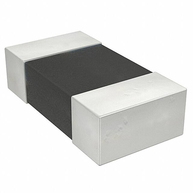


 工商网监
湘ICP备2023018690号
工商网监
湘ICP备2023018690号
