NOT RECOMMENDED FOR NEW DESIGN
AP1184
4A ULTRA LOW DROPOUT POSITIVE ADJUSTABLE OR
FIXED-MODE REGULATOR
General Description
Features
0.85V maximum dropout voltage at 4A load current
Built-in Thermal shutdown
Output current limiting
Adjustable or fixed output voltage1.5V, 1.8V, 2.5V,
3.3V, 5.0V
Fast transient response
Good noise rejection
Packages: TO220-5L and TO263-5L
Lead Free Finish/ RoHS Complian (Note 1)
AP1184 is a 4A regulator with extremely low dropout voltage.
This product is specifically designed to provide well regulated
supply for applications requiring 2.8V or lower voltages from 3.3V
ATX power supplies where high efficiency of the switch can be
achieved without the cost and complexity associated with
switching regulator. One such application is the new graphic
chipsets that requires anywhere from 2.4V to 2.7V supply.
Ordering Information
AP1184 XX - XX L - X
Package
Vout
Lead Free
Packing
K5 : TO263-5L
T5 : TO220-5L
Blank : Adj
15 = 1.5V
18 = 1.8V
25 = 2.5V
33 = 3.3V
50 = 5.0V
L : Lead Free
U : Tube
13 : Tape & Reel
Device
Lead-free
Lead-free
AP1184K5XXL-U
AP1184K5XXL-13
AP1184T5XXL-U
Package
Code
Packaging
(Note 2)
K5
K5
T5
TO263-5L
TO263-5L
TO220-5L
Tube
Part Number
Quantity
Suffix
50
-U
NA
NA
50
-U
13” Tape and Reel
Part Number
Quantity
Suffix
NA
NA
800/Tape & Reel
-13
NA
NA
Lead-free
Notes:
1. EU Directive 2002/95/EC (RoHS). All applicable RoHS exemptions applied, see EU Directive 2002/95/EC Annex Notes.
2. Pad layout as shown on Diodes Inc. suggested pad layout document AP02001, which can be found on our website at
http://www.diodes.com/datasheets/ap02001.pdf.
AP1184 Rev. 6 - 3
1 of 12
www.diodes.com
OCTOBER 2014
© Diodes Incorporated
�NOT RECOMMENDED FOR NEW DESIGN
AP1184
4A ULTRA LOW DROPOUT POSITIVE ADJUSTABLE OR
FIXED-MODE REGULATOR
Pin Assignments
FRONT VIEW
FRONT VIEW
5
4
3
2
1
Vin
Vctrl
Vout
Adj(GND)
Vsense
Vin
Vctrl
Vout
Adj(GND)
Vsense
5
4
3
2
1
Tab is Vout
Tab is Vout
TO263-5L
TO220-5L
Pin Descriptions
Pin Numbers with standard type are for TO220-5L, TO263-5L packages.
Name
I/O
Description
Adj
A resistor divider from this pin to the Vout pin and ground sets the output voltage. (GND
(GND)
only for fixed mode)
This pin is the positive side of the reference that allows remote load sensing to achieve
Vsense
I
excellent load regulation. A minimum of 10uF capacitor must be connected from this pin
to ground to insure stability.
The input of the regulator. Typically a large storage capacitor is connected from this pin
to ground to insure that the input voltage does not sag below the minimum dropout
Vin
I
voltage during the load transient response. This pin must always be higher than Vout in
order for the device to regulate.
This pin is the supply pin for the internal control circuit as well as the base drive for the
pass transistor. This pin must always be higher than the Vout pin in order to regulate the
Vctrl
I
device. A minimum of 100uF capacitor must be connected from this pin to ground to
insure stability.
The output of the regulator. A minimum of 100uF capacitor must be connected from this
Vout
O
pin to ground to insure stability.
Block Diagram
Vin
Vout
Vsense
Vctrl
+
+
-
1.25V
+
CURRENT
LIMIT
+
AP1184 Rev. 6 - 3
-
THERMAL
SHUTDOWN
2 of 12
www.diodes.com
Adj
OCTOBER 2014
© Diodes Incorporated
�NOT RECOMMENDED FOR NEW DESIGN
AP1184
4A ULTRA LOW DROPOUT POSITIVE ADJUSTABLE OR
FIXED-MODE REGULATOR
Typical Application Circuit
(1) Adjustable Regulator
5V
3.3V
470µF
470µF
Vin
Vctrl
Vout
2.5V/ 4A
R1 121 Ω
Adj
470µF
R2 121 Ω
Vsense
Tab is Vout
R
Note : V
V
(1 2 )
OUT
REF
R
1
(2) 3.3V to 2.5V Fixed Mode Regulator
5V
3.3V
470µF
470µF
Vin
Vctrl
2.5V/ 4A
Vout
GND
470µF
Vsense
Tab is Vout
Absolute Maximum Ratings
Symbol
VIN
Vctrl
PD
TST
TOP
Parameter
Input Voltage
Control Input voltage
Power dissipation
Storage temperature Range
Operation Junction Temperature Range
AP1184 Rev. 6 - 3
3 of 12
www.diodes.com
Rating
Unit
16
18
Internally limited
-65 to +150
0 to +125
V
V
o
C
C
o
OCTOBER 2014
© Diodes Incorporated
�NOT RECOMMENDED FOR NEW DESIGN
AP1184
4A ULTRA LOW DROPOUT POSITIVE ADJUSTABLE OR
FIXED-MODE REGULATOR
Electrical Characteristics
(Under Operating Conditions)
Unless otherwise specified, these specifications apply over, Cin = 1uF, Cout = 10uF, and Tj = 0 to 150oC. Typical value refer to TA = 25oC.
Vout = Vsense
Sym.
Parameter
Test Condition
Min
Typ.
Max
Unit
1.225 1.250
1.275
V
0.2
%
1.470 1.500
1.530
V
1.764 1.800
1.836
V
2.450 2.500
2.550
V
3.235 3.300
3.365
V
4.900 5.000
5.100
V
1
%
12
15
mV
15
18
mV
20
25
mV
26
33
mV
40
50
mV
1.10
1.15
1.18
1.25
0.26
0.50
0.70
0.38
0.60
0.85
o
VREF Reference Voltage
Line Regulation
Vout
Output Voltage
Load
Regulation
Dropout Voltage
(Vctrl –Vout)
Dropout Voltage
(Vin – Vout)
Io =10mA, TA = 25 C, (Vin-Vout) = 0.7V,
AP1184-Adj
Vctrl = VIN+1V
o
I = 10mA, VOUT+0.7V
很抱歉,暂时无法提供与“AP1184K5-15L-U”相匹配的价格&库存,您可以联系我们找货
免费人工找货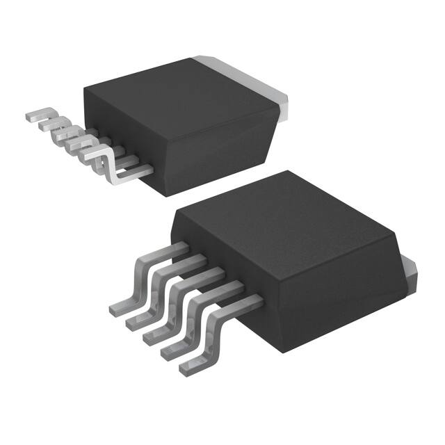


 工商网监
湘ICP备2023018690号
工商网监
湘ICP备2023018690号
