ADVANCED INFORMATION
A product Line of
Diodes Incorporated
FH Series Quartz Crystal Legacy NKS2 Series
2.5 x 2.0mm
FH
Miniature Quartz Crystal Ceramic SMD
2.5 x 2.0mm Ceramic SMD
Package: (Scale: non; dimensions are in mm)
2.5 ± 0.1
Recommended Land Pattern:
Product Description
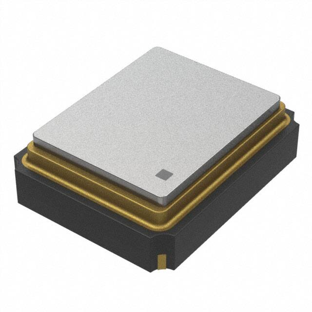
The 4-pad FH Series seam seal devices incorporate
a sub-miniature AT-cut crystal resonator housed in
a standard 2.5 x 2.0mm ceramic package. These
compact crystals are ideal for surface mounting
in densely populated or small form-factor PCB
applications.
0.6
2.0 ± 0.1
0.95
1.0
0.85
CREATED USING CADSTD LITE FREEWARE FROM WWW.CADSTD.COM. NON-COMMERCIAL USE ONLY.
Product Features
• Rugged AT-cut crystal construction
0.6 ± 0.1
• Miniature 2.5 x 2.0mm ceramic package
• Available on tape & reel; 8mm tape,
3000 units per reel
0.9
0.72
• Pb-free and RoHS/Green compliant
1
2
Pin Functions:
Pin
Function
1
Xtal
2
Case
3
Xtal
4
Case
Typical Applications
0.7
• Portable / Hand-held PCs
• PCMCIA Cards
4
• Notebook PC
3
0.57
• Bluetooth
• Wireless LAN
• UWB
Part Ordering Information:
• ZigBee
FH XXX YYYY
• USB
• GPS
• HDD
A: Product�Family
B: XXX = Frequency�Code
C: YYYY = Specification�Code
• GSM, CDMA, GPRS
Following the above format, Saronix-eCera part numbers will be assigned upon
confirmation of exact customer requirements.
© Diodes Incorporated
FH SERIES
Document Number. 40267 Rev 1-2
•
US: +1-408-232-9100 TW: +886-3-4518888 • www.diodes.com
1
October 2017
© Diodes Incorporporated
�Miniature Quartz Crystal Ceramic SMD
FH
FH Series Quartz Crystal
Legacy NKS2 Series | 2.5 x 2.0mm
A product Line of
Diodes Incorporated
Frequency Range:
Mechanical
• 12 MHz to 66.0000 MHz (Fundamental)
•Shock: JESD22-B104 Condition B
•Solderability: J-STD-002
Characteristics at 25°C ±2°C:
• Frequency Calibration Tolerance: ±10ppm, ±20ppm, or
±30ppm
•Terminal Strength: MIL-STD-883 Method 2004
• Load Capacitance: 7 to 32pF or Series Resonance
•Solvent Resistance: JESD22-B107
• Effective Series Resistance (ESR):
150Ω max (12 to 19.9 MHz)
80Ω max (20 to 29.9 MHz)
60Ω max (30 to 66 MHz)
•Vibration: JESD22-B103
•Resistance to Soldering Heat: J-STD-020C Table 5-2 Pb-free
devices (3 cycles max)
Environmental
•Gross Test Leak: JESD22-A109, Condition C
• Drive Level: 10µW typ. (100µW max)
•Fine Test Leak: JESD22-A109, Condition A1
• Shunt Capacitance: 5pF Max
•Moisture Resistance: JESD22-A113
•Insulation Resistance: 500 MΩ min (100 VDC)
Temperature Range:
• Operating: –20 to +70°C or –40 to +85°C or –40 to +125°C
• Storage: –55 to +125
Temperature Stability:
• ±10ppm, ±20ppm, ±30ppm, or ±50ppm (–20 to +70°C)
• ±30ppm, or ±50ppm (–40 to +85°C)
•±50ppm, or ±70ppm (–40 to 125°C)
Aging at 25°C, First Year:
•±3ppm Max
Reflow Temperature:
•260°C Max, 10 seconds Max
Legacy Ordering Information - For Reference Only:
NKS
2
NAD 1
– 25.0000
–20
(T)
SaRonix Series Designator
NKS = 4 pad seam seal
Packing Method
(T) = Tape & Reel, full reel
increments only, 3000pcs
Blank = Bulk
Package Type
2 (2.5 x 2.0 mm typ)
Load Capacitance
–XX = Load Capacitance
Calibration / Stability / Temp Range
HAA = ±10 ppm / ±10 ppm / -20°C to +70°C
JAB = ±20 ppm / ±20 ppm / -20°C to +70°C
NAD = ±30 ppm / ±30 ppm / -20°C to +70°C
NAK = ±30 ppm / ±50 ppm / -20°C to +70°C
NED = ±30 ppm / ±30 ppm / -40°C to +85°C
NEK = ±30 ppm / ±50 ppm / -40°C to +85°C
Part Number Example:
Frequency
Frequencies (in MHz) = xx.xxxx
Mode
1 = Fundamental
Spec: Freq 20MHz, ±30ppm calib, ±30ppm stab, -20 to +70°C, 16pF, T&R = NKS2NAD1-20.0000-16(T)
© Diodes Incorporated
FH SERIES
Document Number. 40267 Rev 1-2
•
US: +1-408-232-9100 TW: +886-3-4518888 • www.diodes.com
2
October 2017
© Diodes Incorporporated
�Miniature Quartz Crystal Ceramic SMD
FH
FH Series Quartz Crystal
Legacy NKS2 Series | 2.5 x 2.0mm
A product Line of
Diodes Incorporated
IMPORTANT NOTICE
DIODES INCORPORATED MAKES NO WARRANTY OF ANY KIND, EXPRESS OR IMPLIED, WITH REGARDS TO THIS DOCUMENT, INCLUDING, BUT NOT
LIMITED TO, THE IMPLIED WARRANTIES OF MERCHANTABILITY AND FITNESS FOR A PARTICULAR PURPOSE (AND THEIR EQUIVALENTS UNDER THE
LAWS OF ANY JURISDICTION).
Diodes Incorporated and its subsidiaries reserve the right to make modifications, enhancements, improvements, corrections or other changes without further notice
to this document and any product described herein. Diodes Incorporated does not assume any liability arising out of the application or use of this document or any
product described herein; neither does Diodes Incorporated convey any license under its patent or trademark rights, nor the rights of others. Any Customer or user of
this document or products described herein in such applications shall assume all risks of such use and will agree to hold Diodes Incorporated and all the companies
whose products are represented on Diodes Incorporated website, harmless against all damages.
Diodes Incorporated does not warrant or accept any liability whatsoever in respect of any products purchased through unauthorized sales channel.
Should Customers purchase or use Diodes Incorporated products for any unintended or unauthorized application, Customers shall indemnify and hold Diodes Incorporated and its representatives harmless against all claims, damages, expenses, and attorney fees arising out of, directly or indirectly, any claim of personal injury or
death associated with such unintended or unauthorized application.
Products described herein may be covered by one or more United States, international or foreign patents pending. Product names and markings noted herein may
also be covered by one or more United States, international or foreign trademarks.
This document is written in English but may be translated into multiple languages for reference. Only the English version of this document is the final and determinative format released by Diodes Incorporated.
LIFE SUPPORT
Diodes Incorporated products are specifically not authorized for use as critical components in life support devices or systems without the express written approval of
the Chief Executive Officer of Diodes Incorporated. As used herein:
A. Life support devices or systems are devices or systems which:
1. are intended to implant into the body, or
2. support or sustain life and whose failure to perform when properly used in accordance with instructions for use provided in the labeling can be reasonably expected
to result in significant injury to the user.
B. A critical component is any component in a life support device or system whose failure to perform can be reasonably expected to cause the
failure of the life support device or to affect its safety or effectiveness.
Customers represent that they have all necessary expertise in the safety and regulatory ramifications of their life support devices or systems, and acknowledge and
agree that they are solely responsible for all legal, regulatory and safety-related requirements concerning their products and any use of Diodes Incorporated products
in such safety-critical, life support devices or systems, notwithstanding any devices- or systems-related information or support that may be provided by Diodes Incorporated. Further, Customers must fully indemnify Diodes Incorporated and its representatives against any damages arising out of the use of Diodes Incorporated
products in such safety-critical, life support devices or systems.
Copyright © 2016, Diodes Incorporated
www.diodes.com
© Diodes Incorporated
FH SERIES
Document Number. 40267 Rev 1-2
•
US: +1-408-232-9100 TW: +886-3-4518888 • www.diodes.com
3
October 2017
© Diodes Incorporporated
�


 工商网监
湘ICP备2023018690号
工商网监
湘ICP备2023018690号
