物料型号:PI3USB9281A
器件简介:
- 提供外部USB设备检测
- 集成了具有过压和过流保护的电源开关
- VBUSIN输入引脚可承受高达28V的电压,适用于USB 3.0 Power Delivery端口
- 工作温度范围为-40至+85°C
- 适用于便携式和消费类应用,如平板电脑、智能手机、数码相机和笔记本电脑
引脚分配:
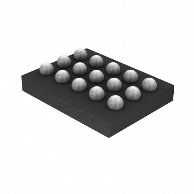
- 提供了两种封装:CSP 1.5x2.0-15L和UQFN 3x4x0.5mm 20L
- 引脚包括电源路径、信号路径、充电接口和I2C接口等
参数特性:
- 存储温度范围:-65°C至+150°C
- 电源电压范围:从电池/基带为-0.5V至+6.5V,从Micro-USB连接器为-0.5V至+28.0V
- ESD防护等级:HBM 3500V
功能详解:
- 可检测多种市场上的充电器、MHL配件、OTG配件和符合CEA936规格的车充
- 集成的电源FET提供1.7A过流保护(OCP)和VBUS过压保护(OVP)
- 支持USB On-The-Go (OTG)检测和Mobile HDMI Link (MHL)设备检测
- 宽电源电压范围:3V至5.5V
- I2C可编程性
应用信息:
- 适用于个人媒体播放器、手机和平板电脑等
封装信息:
- 提供了两种封装选项,包括CSP和UQFN,具体尺寸和引脚布局在文档中有详细描述


 工商网监
湘ICP备2023018690号
工商网监
湘ICP备2023018690号

