PI6C2410
12345678901234567890123456789012123456789012345678901234567890121234567890123456789012345678901212345678901234567890123456789012123456789012
12345678901234567890123456789012123456789012345678901234567890121234567890123456789012345678901212345678901234567890123456789012123456789012
PCI-X Clock Buffers
Product Features
•
•
•
•
•
•
•
•
•
•
Product Description
Four synchronous outputs
Selectable divider/multiplier
Output Enable control
Low phase error < 150 ps
Allows clock input to have spread spectrum modulation for
EMI reduction
Low output skew < 200 ps
Low cycle jitter < 200 ps
Industrial temperature (–40°C to 85°C)
3.3V supply
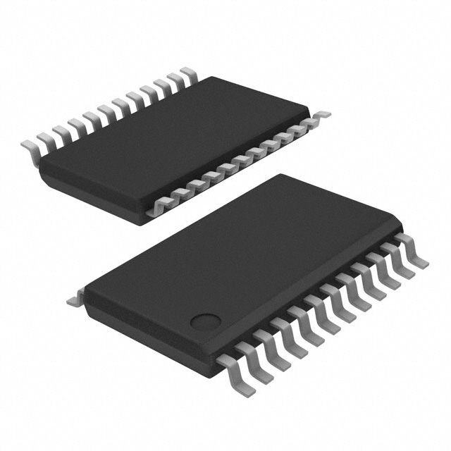
Packages (Pb-free and Green available):
24-pin QSOP (Q)
24-pin TSSOP (L)
PI6C2410 is a low skew, low jitter, PLL clock buffer with divider or
multiplier designed for PCI-X application in servers and workstations. There are two selectable input ranges using HF# input: 10-40
MHz and 40-80 MHz. All outputs are synchronized to the input and
to the other outputs. Each output can be independently turned off
to reduce EMI and power consumption.
Pin Configuration
AGND
1
24
CLKIN
VCC
2
23
AVCC
HF#
3
22
VCC
DIV0
4
21
OUT0
DIV1
5
20
OUT1
GND
Block Diagram
6
24-Pin
Q, L 19
GND
GND
7
18
GND
FBIN
8
17
OUT2
FBOUT
9
16
OUT3
VCC
10
15
VCC
OE0
11
14
OE3
OE1
12
13
OE2
OUT0
OUT1
OUT2
OE[0:3]
HF#
OUT3
CLKIN
FBIN
PLL
DIV
FBOUT
Clock Select Table
DIV[0:1]
HF#
DIV1
DIV0
OUTx
1
1
1
CLKIN
1
1
0
2xCLKIN
CLKIN
OUTx
33MHz
66MHz
33MHz
1
0
1
3xCLKIN
100MHz
1
0
0
4xCLKIN
133MHz
0
1
1
CLKIN/2
33MHz
0
1
0
CLKIN
66MHz
66MHz
09-0006
1
0
0
1
1.5xCLKIN
100MHz
0
0
0
2xCLKIN
133MHz
PS8593C
11/17/09
�PI6C2410
PCI-X
Clock
Buffers
12345678901234567890123456789012123456789012345678901234567890121234567890123456789012345678901212345678901234567890123456789012123456789012
12345678901234567890123456789012123456789012345678901234567890121234567890123456789012345678901212345678901234567890123456789012123456789012
Pin Description
Pin
Type
Qty
Symbol
De s cription
21,20,17,16
O
4
OUT[0:3]
Clock outputs. To achieve zero input to output delay, all outputs must have the
same loading.
11, 12, 13,
14
I
4
OE[0:3]
Active high Output Enable, pulled up. When OE is low, OUT [0:3] outputs are
disabled at low state.
9
O
1
FBOUT
Feedback output. To achieve zero input to output delay, FBOUT must have the
same loading as OUT[0:3].
8
I
1
FBIN
24
I
1
CLKIN
3
I
1
HF#
4,5
I
2
DIV[0,1]
2,10,15,22
P
4
VC C
3.3V power
6,7,18,19
P
4
GND
Ground
23
P
1
AVC C
3.3V analog power
1
P
1
AGND
Analog ground
Feedback input.
Input Clock.
High Frequency range, pulled up.
"1" = Low, "0" = High.
Divider/Multiplier Select, pulled up.
Absolute Maximum Ratings
Supply Voltage (VCC, AVCC) ................................................ 0.5V to +4.6V
Input Voltage ................................................................ –0.5V to Vcc+0.5V
Industrial Operating Temperature ....................................... -40°C to +85°C
Storage Temperature ........................................................ –65°C to +150°C
Junction Temperature ....................................................................... 150°C
Input ESD MIL-883, Method 3015, human body model ....................... 2kV
Operating Condition
Symbol
VCC, AVCC
TA
09-0006
De s cription
M in.
M ax.
Units
I/O Supply, Analog Core Supply
3.0
3.6
V
Industrial Ambient Temperature
–40
+85
°C
2
PS8593C
11/17/09
�PI6C2410
PCI-X
Clock
Buffers
12345678901234567890123456789012123456789012345678901234567890121234567890123456789012345678901212345678901234567890123456789012123456789012
12345678901234567890123456789012123456789012345678901234567890121234567890123456789012345678901212345678901234567890123456789012123456789012
DC Electrical Characteristics Over Operating Conditions
Symbol
Parame te r
Conditions
M in.
Typ.
M a x.
VIL
Low Input Voltage
VIH
High Input Voltage
IIL
Low Input Current
VIN = 0V
50
IIH
High Input Current
VIN = VCC
200
VOL
Low Output Voltage
VCC = 3.0V, Iol = 12mA
0. 4
VOH
High Output Voltage
VCC = 3.0V, Ioh = –12mA
Idd_33
Supply Current
CL = 15pF, FOUT = 33MHz
25
Idd_66
Supply Current
CL = 15pF, FOUT = 66MHz
35
Idd_100
Supply Current
CL = 15pF, FOUT = 100MHz
45
Idd_133
Supply Current
CL = 15pF, FOUT = 133MHz
60
Units
0.8
V
2.0
uA
V
2 .4
tbd
mA
CO
Output Capacitance
6
CI
Input Capacitance
6
Pin Inductance
7
nH
Units
pF
LPIN
Switching Characteristics (TA = 25°C, VCC = 3.3V ±0.3V, Cl = 15pF, FOUT = 66.67 MHz)
Symbol
Parame te r
Te s t Conditions
M in.
Typ.
M a x.
Low Freq., HF# = "1"
10
33
40
High Freq., HF# = "0"
40
66
80
Input frequency
FIN
FOUT
Output frequency
TPD
Propagation delay
CLKIN to FBIN rising edges @VDD/2
TSK
Output skew
@1.4V, rising edges
20 0
TSKPP
Pkg to pkg skew
@VDD/2, rising edges, same CLKIN
40 0
TJC
Cycle jitter
TDC
Duty cycle
@ 1. 4 V
TR/TF
Rise/Fall time
0.8V~2.0V
MHz
160
–150
150
ps
200
35
50
65
%
1. 5
ns
Note: Tjc = Tp(n+1) –Tp(n)
Tdc = Th/Tp
Tp(n) = Period of the nth cycle
Tp = Period cycle time
Tp(n+1) = Period of nth+1 cycle Th = High time @1.4V
09-0006
3
PS8593C
11/17/09
�PI6C2410
PCI-X
Clock
Buffers
12345678901234567890123456789012123456789012345678901234567890121234567890123456789012345678901212345678901234567890123456789012123456789012
12345678901234567890123456789012123456789012345678901234567890121234567890123456789012345678901212345678901234567890123456789012123456789012
2.0V
T1
2.0V
0.8V
0.8V
Tr
1.4V
Tf
Tp
Figure 1. Rise/Fall time
Figure 2. Duty cycle
1.4V
Tp(n)
OUTx
1.65V
Tsk
OUTy
1.65V
1.4V
Tp(n+1)
Figure 4. Cycle jitter
Figure 3. Output skew
Device1
OUTx
1.65V
CLKIN
Tpd
Tskp2p
Device2
OUTy
1.65V
1.65V
FBIN
1.65V
Figure 6. Propagation Delay
Figure 5. Pkg.-to-Pkg. skew
DUT
OUTx
15pF
Figure 7. Test load
09-0006
4
PS8593C
11/17/09
�PI6C2410
PCI-X
Clock
Buffers
12345678901234567890123456789012123456789012345678901234567890121234567890123456789012345678901212345678901234567890123456789012123456789012
12345678901234567890123456789012123456789012345678901234567890121234567890123456789012345678901212345678901234567890123456789012123456789012
Packaging Mechanical: 24-Pin TSSOP (L)
DOCUMENT CONTROL NO.
PD - 1312
24
REVISION: E
DATE: 03/09/05
.169
.177
4.3
4.5
.004
.008
1
.303
.311
7.7
7.9
0.45
0.75
1
.047
1.20
Max
.0256
BSC
0.65
.007
.012
0.19
0.30
.002
.006
SEATING
PLANE
0.09
0.20
.018
.030
.252
BSC
6.4
0.05
0.15
Pericom Semiconductor Corporation
3545 N. 1st Street, San Jose, CA 95134
1-800-435-2335 • www.pericom.com
Note:
1. Package Outline Exclusive of Mold Flash and Metal Burr
2. Controlling dimentions in millimeters
3. Ref: JEDEC MO-153F/AD
DESCRIPTION: 24-Pin, 173-Mil Wide, TSSOP
PACKAGE CODE: L
09-0006
5
PS8593C
11/17/09
�PI6C2410
PCI-X
Clock
Buffers
12345678901234567890123456789012123456789012345678901234567890121234567890123456789012345678901212345678901234567890123456789012123456789012
12345678901234567890123456789012123456789012345678901234567890121234567890123456789012345678901212345678901234567890123456789012123456789012
Packaging Mechanical: 24-pin QSOP (Q)
DOCUMENT CONTROL NO.
3'�������
24
REVISION: H
.008
0.20
MIN.
.150
.157
3.81
3.99
Guage Plane
.010
0.254
.041
1.04
REF
8.56
8.74
.033
0.84
�Û��Û
.016
.035
0.41
0.89
Detail A
1
.337
.344
DATE: 10/22/07
.008
.013
0.20
0.33
.053
.069
�����[���Û
0.38
1.35
1.75
Detail A
1
.007
.010
0.178
0.254
SEATING
PLANE
.025
typical
0.635
.008 0.203
.012 0.305
.004 0.101
.010 0.254
.228
.244
5.79
6.20
X.XX DENOTES DIMENSIONS
X.XX IN MILLIMETERS
Pericom Semiconductor Corporation
3545 N. 1st Street, San Jose, CA 95134
�������������� • www.pericom.com
Note:
1) Controlling dimensions in millimeters
2) Ref:�-('(&��02����%�$(
3) Dimensions do not include mold flash, protrusions or gate burrs
DESCRIPTION:����3LQ,�����0LO Wide, QSOP
PACKAGE CODE: Q
�������
Notes:
• For latest package info, please check: http://www.pericom.com/products/packaging/mechanicals.php
Ordering Information
Orde ring Code
Package Name
Package Type
PI6C2410QEX
Q
Pb- free & Green, 24- pin, 150- mil QSOP
PI6C2410LEX
L
Pb- free & Green, 24- pin, 173- mil TSSOP
Notes:
• Thermal characteristics can be found on the company web site at www.pericom.com/packaging/
• E = Pb-free and Green
• Adding an X suffix = Tape/Reel
Pericom Semiconductor Corporation • 1-800-435-2336 • http://www.pericom.com
09-0006
6
PS8593C
11/17/09
�