Data Sheet
PT7V4027 VCXO
|||||||||||||||||||||||||||||||||||||||||||||||||||||||||||||||||||||||||||||||||||||||||||||||||||||||||||||||||||||||||||||||||||||||||||||||||||||||||||||||||||||||||||||||||||||||||||||||||||||||||||||||||||||||||||||||||||||||||||||||||||||||||||||||||||||||||||||||||||||||||||||||||||||||||||||||||||||||||||||||||||||||
Product Features
General Description
•
•
•
•
•
•
•
The PT7V4027 is a low-cost, high-performance VCXO,
designed to replace expensive VCXO modules. The on-chip
voltage causes clocks to vary by ±120ppm. It uses an
3.3V or 5V operating voltage
Uses an inexpensive external crystal
Provide clock output enable
On-chip VCXO with pull range of 240ppm
VCXO tuning voltage from 0 to Vcc
10mA output driver at CMOS levels (3.3V Vcc)
Available in SOIC package and die form
inexpensive external pullable crystal at 27MHz to
produce the same output frequency.
Applications
Set-Top Box
xDSL
z
Ordering Information
z
Ordering code
Package type
PT7V4027W
PT7V4027WE
PT7V4027DE
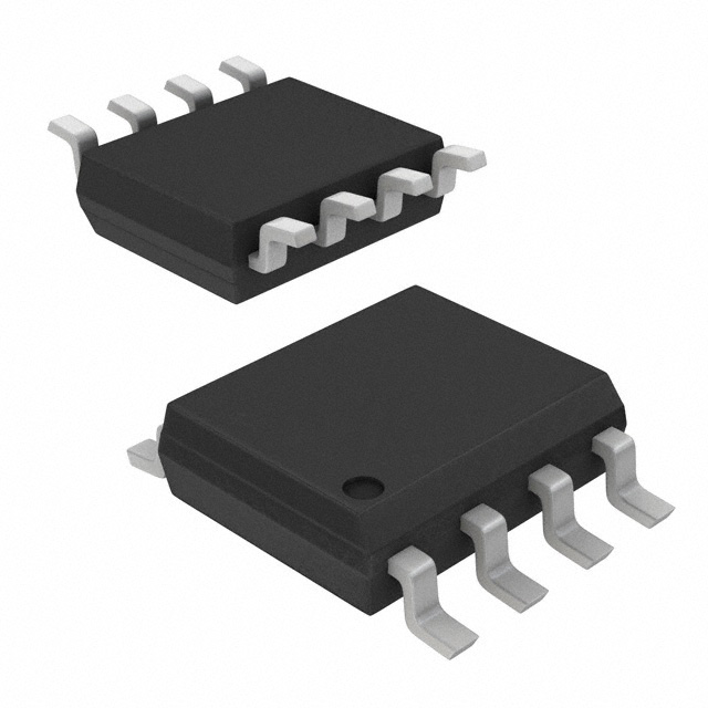
8-Pin SOIC
8-Pin SOIC lead free
Die Form
Operating
Range
Industrial
Industrial
Industrial
Logic Block Diagram
OE
Pin Configuration
8
X2
7
OE
3
6
Vcc
4
5
CLKOUT
X1
1
NC
2
VIN
GND
PT7V4027
SOIC 8 package
Pin Description
Pin
Number
1, 8
2
3
4
5
6
7
Pin Name
Type
X1, X2
NC
VIN
GND
CLKOUT
VCC
OE
I
I
PWR
O
PWR
I
Description
Crystal Connection, Connect to a pullable 27MHz crystal
No Connect, Can be float or connected to VCC or GND
Voltage Input to VCXO
Ground
Clock Output
Power Supply +3.3V or 5V
Output Enable. High or floating enables output. Internal pull-up.
PT0147(3/05)
Ver: 4
1
�Data Sheet
PT7V4027 VCXO
|||||||||||||||||||||||||||||||||||||||||||||||||||||||||||||||||||||||||||||||||||||||||||||||||||||||||||||||||||||||||||||||||||||||||||||||||||||||||||||||||||||||||||||||||||||||||||||||||||||||||||||||||||||||||||||||||||||||||||||||||||||||||||||||||||||||||||||||||||||||||||||||||||||||||||||||||||||||||||||||||||||||
Pad Location
1300
X1
X2
OE
Vcc
1250
VIN
Vcc
NC
CLKOUT
GND
GND
Note: substrate should be tied to GND or floating.
Pad Name
CLKOUT
Vcc
Vcc
OE
X2
X Coordinates
553.05
511.75
511.75
554.1
312.55
Pad Coordinates
Y Coordinates
Pad Name
-316.55
X1
-79.35
VIN
20.75
OE
199.75
GND
479.75
GND
PT0147(3/05)
X Coordinates
-511.55
-534.3
-534.3
-534.3
-375.95
Y Coordinates
479.75
-124.7
-305.6
-469.4
-496.4
Ver: 4
2
�Data Sheet
PT7V4027 VCXO
|||||||||||||||||||||||||||||||||||||||||||||||||||||||||||||||||||||||||||||||||||||||||||||||||||||||||||||||||||||||||||||||||||||||||||||||||||||||||||||||||||||||||||||||||||||||||||||||||||||||||||||||||||||||||||||||||||||||||||||||||||||||||||||||||||||||||||||||||||||||||||||||||||||||||||||||||||||||||||||||||||||||
Maximum Ratings
(Above which the useful life may be impaired. For user
guidelines, not tested.)
Storage Temperature………………..-55oC to 125oC
Ambient Temperature…………….….-40oC to 85oC
Supply Voltage VCC
…………….…. … -0.5V to 7V
Input Voltage……………………-0.5V to VCC+0.5V
Output Current ……………………………….10mA
Soldering Lead Temperature(10s)…………….260oC
Note:
Stresses greater than those listed under MAXIMUM
RATINGS may cause permanent damage to the device.
This is a stress rating only and functional operation of the
device at these or any other conditions above those
indicated in the operational sections of this specification
is not implied. Exposure to absolute maximum rating
conditions for extended periods may affect reliability.
DC Electrical Characteristics
(Unless otherwise specified, VCC = 3.3 or 5V, fO = 27MHz, VIN = VCC/2, Load = 15pF, TA = 25oC)
Sym.
Parameter
Test Condition
Pin
Min.
Vcc
3.153
Typ.
Max.
Unit
5.25
V
Vcc
Supply Voltage
ICC
Supply Current
IDDS
Supply Current
VIH
Input Logic High
OE
VIL
Input Logic Low
OE
IOH
High-level output voltage
IOL
Low-level output voltage
VOL = 0.5V
IOZ
Output Leakage Current
OE = 0V
CLKOUT
Negative Resistance
VIN = 0V
X1, X2
Vcc=5.0V
X1, X2
20
27
40
Vcc=3.3V
X1, X2
15
27
40
15
30
RS
*
f
CL
Input Frequency
Vcc = 3.3V, CL = 15pF
Vcc
5
Vcc = 5V, CL = 15pF
OE = 0V
VOH = Vcc -0.5V
mA
8
Vcc
1
2.0
V
0.8
Vcc=3.3V
CLKOUT
-11
-4
Vcc=5V
CLKOUT
-18
-8
Vcc=3.3V
CLKOUT
4
12
Vcc=5V
CLKOUT
8
18
Output Capacitance
10
V
mA
µA
Ω
-150
CLKOUT
mA
MHz
pF
* Note: only reference for design.
AC Electrical Characteristics
(Unless otherwise specified, VCC = 3.3 or 5V, fO = 27MHz, Load = 15pF, TA = 25oC)
Sym.
Parameter
Test Condition
Vcc=3.3V
tr / tf
Rise / Fall time
Pin
Min.
CLKOUT
Typ.
Max.
1.5
6
1.0
3
50
55
0.1VCC to 0.9VCC
ns
Vcc=5V
Duty
Output clock duty cycle
At VCC/2
∆f
Output frequency pull range
VIN from 0V to VCC
tj
Cycle to cycle jitter
Unit
CLKOUT
45
±120
ppm
50
ps
%
Linearity
VIN from 0.1 to 0.9VCC
±10
Oscillator start time
Trigger at 0.9VCC
1.5
PT0147(3/05)
%
10
ms
Ver: 4
3
�Data Sheet
PT7V4027 VCXO
|||||||||||||||||||||||||||||||||||||||||||||||||||||||||||||||||||||||||||||||||||||||||||||||||||||||||||||||||||||||||||||||||||||||||||||||||||||||||||||||||||||||||||||||||||||||||||||||||||||||||||||||||||||||||||||||||||||||||||||||||||||||||||||||||||||||||||||||||||||||||||||||||||||||||||||||||||||||||||||||||||||||
Recommended Crystal Specifications
Description
Mode of Oscillation
Frequency Range
Frequency Tolerance
Temperature plus Aging Stability
Operating Temperature
C0/C1
Load Capacitance(CL)
Equivalent Series Resistance(ESR)
Crystal
Fundamental
27.000MHz
±30ppm
±50ppm
-20ºC to + 70ºC
240(max.)
18pF
35ohms(max.)
PT0147(3/05)
Ver: 4
4
�Data Sheet
PT7V4027 VCXO
|||||||||||||||||||||||||||||||||||||||||||||||||||||||||||||||||||||||||||||||||||||||||||||||||||||||||||||||||||||||||||||||||||||||||||||||||||||||||||||||||||||||||||||||||||||||||||||||||||||||||||||||||||||||||||||||||||||||||||||||||||||||||||||||||||||||||||||||||||||||||||||||||||||||||||||||||||||||||||||||||||||||
Plastic 8-pin SOIC (W) Package
PT0147(3/05)
Ver: 4
5
�Data Sheet
PT7V4027 VCXO
|||||||||||||||||||||||||||||||||||||||||||||||||||||||||||||||||||||||||||||||||||||||||||||||||||||||||||||||||||||||||||||||||||||||||||||||||||||||||||||||||||||||||||||||||||||||||||||||||||||||||||||||||||||||||||||||||||||||||||||||||||||||||||||||||||||||||||||||||||||||||||||||||||||||||||||||||||||||||||||||||||||||
Notes
Pericom Technology Inc.
Email: support@pti.com.cn
Web Site: www.pti.com.cn, www.pti-ic.com
China:
No. 20 Building, 3/F, 481 Guiping Road, Shanghai, 200233, China
Tel: (86)-21-6485 0576
Fax: (86)-21-6485 2181
Asia Pacific:
Unit 1517, 15/F, Chevalier Commercial Centre, 8 Wang Hoi Rd, Kowloon Bay, Hongkong
Tel: (852)-2243 3660
Fax: (852)- 2243 3667
U.S.A.:
3545 North First Street, San Jose, California 95134, USA
Tel: (1)-408-435 0800
Fax: (1)-408-435 1100
Pericom Technology Incorporation reserves the right to make changes to its products or specifications at any time, without notice, in order to improve design or
performance and to supply the best possible product. Pericom Technology does not assume any responsibility for use of any circuitry described other than the
circuitry embodied in Pericom Technology product. The company makes no representations that circuitry described herein is free from patent infringement or
other rights, of Pericom Technology Incorporation.
PT0147(3/05)
Ver: 4
6
�
很抱歉,暂时无法提供与“PT7V4027WEX”相匹配的价格&库存,您可以联系我们找货
免费人工找货