SR502 - SR506
HIGH CURRENT SCHOTTKY BARRIER RECTIFIER
NOT RECOMMENDED FOR NEW DESIGNS,
PLEASE USE SB520 - SB560
Features
·
·
·
·
·
High Current Capability and Low Forward Drop
High Surge Capacity
Guard Ring for Transient Protection
Low Power Loss, High Efficiency
Plastic Material: UL Flammability
Classification Rating 94V-0
B
A
A
C
D
Mechanical Data
·
·
·
·
·
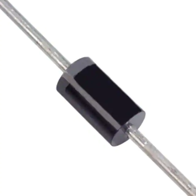
DO-201AD
Case: DO-201AD, Molded Plastic
Terminals: Axial Lead, Solderable per
MIL-STD-202, Method 208
Mounting Position: Any
Polarity: Cathode Band
Weight: 1.20 grams (approx.)
Dim
Min
Max
A
25.40
¾
B
7.20
9.50
C
1.20
1.30
4.80
5.20
D
All Dimensions in mm
Maximum Ratings and Electrical Characteristics
Rating at 25°C ambient temperature unless otherwise specified.
Single phase, half wave, 60Hz, resistive or inductive load.
Symbol
SR502
SR503
SR504
SR505
SR506
Unit
Maximum Recurrent Peak Reverse Voltage
Characteristic
VRRM
20
30
40
50
60
V
Maximum RMS Voltage
VRSM
14
21
28
35
42
V
Maximum DC Blocking Voltage
VDC
20
30
40
50
60
V
Maximum Average Forward Rectified
@ TL = 90°C
Current 9.5mm lead length
Peak Forward Surge current 8.3ms half sine-wave
Superimposed on Rated Load (JEDEC Method)
I(AV)
5.0
A
IFSM
150
A
Maximum Forward Voltage
Maximum Average Reverse Current at
Peak Reverse Voltage
Typical Thermal Resistance (Note 1)
Typical Junction Capacitance (Note 2)
Storage and Operating Temperature Range
Notes:
@ 5.0A
VF
@ TA = 25°C
@ TA = 100°C
IR
IR
0.55
1.0
50
RqJL
15
CJ
550
TJ, TSTG
0.67
-65 to +150
V
mA
10
K/W
400
pF
°C
1. Thermal Resistance from Junction to Lead Vertical PC Board Mounting, 9.5mm Lead Length.
2. Measured at 1.0MHz and applied reverse voltage of 4.0V.
DS23005 Rev. 7 - 3
1 of 2
www.diodes.com
SR502 - SR506
ã Diodes Incorporated
�3
2
1
Single Phase Half Wave
60 Hz Resistive or Inductive Load
0
20
40
60
80
100
120
140
4000
CJ, CAPACITANCE (pF)
TJ = 25ºC
SR502
SR503
SR504
1000
SR505
SR506
100
1.0
10
VR, REVERSE VOLTAGE (VOLTS)
Fig. 3 Typical Junction Capacitance
SR502
SR503
SR504
10
SR505
SR506
1.0
TJ = 25ºC
Pulse Width = 300ms
2% Duty Cycle
0.1
0.1
0.3
0.5
0.7
0.9
1.1
VF, INSTANTANEOUS FORWARD VOLTAGE (VOLTS)
Fig. 2 Typical Forward Characteristics
TL, LEAD TEMPERATURE (ºC)
Fig. 1 Typical Forward Characteristics
0.1
IF, INSTANTANEOUS FORWARD CURRENT (AMPS)
4
40
100
IFSM, PEAK FORWARD SURGE CURRENT (AMPERES)
I(AV), AVERAGE OUTPUT CURRENT (AMPERES)
5
175
8.3ms Single Half Sine-Wave
JEDEC Method
150
125
100
75
50
25
0
1
10
100
NUMBER OF CYCLES AT 60 Hz
Fig. 4 Maximum Non-Repetitive Peak Forward Surge Current
IMPORTANT NOTICE
Diodes Incorporated and its subsidiaries reserve the right to make modifications, enhancements, improvements, corrections or other changes without further
notice to any product herein. Diodes Incorporated does not assume any liability arising out of the application or use of any product described herein; neither
does it convey any license under its patent rights, nor the rights of others. The user of products in such applications shall assume all risks of such use and will
agree to hold Diodes Incorporated and all the companies whose products are represented on our website, harmless against all damages.
LIFE SUPPORT
Diodes Incorporated products are not authorized for use as critical components in life support devices or systems without the expressed written approval of the
President of Diodes Incorporated.
DS23005 Rev. 7 - 3
2 of 2
www.diodes.com
SR502 - SR506
�
很抱歉,暂时无法提供与“SR502-T-F”相匹配的价格&库存,您可以联系我们找货
免费人工找货