IMX70 / IMY70 Series
70 to 90 Watt DC-DC Converters
The IMX/IMY70 Series of board-mountable 70 Watt DC-DC
converters has been designed according to the latest industry
requirements and standards. The converters are particularly
suitable for use in mobile or stationary applications in transport,
railways, industry, or telecommunication, where variable input
voltages or high transient voltages are prevalent.
63.5
2.5"
47.8
1.88"
76.2
3"
72.7
2.86"
12.5
0.49"
Covering 24, 72, 96 & 110 V battery voltages with 2 different
models, the converters are available with one or two electrically
isolated outputs from 5 V to 48 V, externally adjustable and
with flexible load distribution. A shutdown input allows remote
converter on/off. Features include consistently high efficiency
over the entire input voltage range, high reliability, and excellent
dynamic response to load and line changes.
Features
9.75
0.38"
•
•
•
•
•
•
•
•
•
•
•
•
•
•
•
•
•
RoHS-compliant for all six substances
5 year warranty
Extremely wide input voltage ranges up to 154 VDC
1 or 2 isolated outputs up to 48 V
Basic insulation: IMX models
Class I equipment wi th reinforced insulation: IMY models
1500 to 3000 VAC i/o electric strength test voltage
Programmable input undervoltage lockout
Shutdown / inhibit input
Adjustable output voltages with flexible load distribution
Sense lines and current share option
External frequency synchronization
Output(s) no-load, overload, and short-circuit proof
Operating ambient temperature from – 40 to 95 °C
Thermal protection
Planar technology for best stability
Metal case (12.5 mm high) or open frame with 9.75 mm profile
Safety-approved to the latest edition of IEC/EN 60950-1
and UL/CSA 60950-1. CE mark for 110IMY70.
1
1
Table of Contents
Page
Description........................................................................................1
Model Selection.................................................................................2
Functional Description.......................................................................3
Electrical Input Data..........................................................................4
Electrical Output Data.......................................................................6
Auxiliary Functions..........................................................................10
110IMY70
Page
Electromagnetic Compatibility (EMC)..............................................12
Immunity to Environmental Conditions............................................13
Mechanical Data..............................................................................14
Safety and Installation Instructions..................................................15
Options............................................................................................17
belfuse.com/power-solutions
BCD.00002 Rev AJ, 28-May-2018
�IMX70 / IMY70 Series
70 to 90 Watt DC-DC Converters
Description
The converters are designed according to the international safety standards IEC/EN/UL 60950-1 2nd Edition. The 24IMX70
converters exhibit basic insulation for the specified input voltage, whereas the 110IMY70 converters have reinforced insulation.
The circuit is comprised of 2 planar magnetic devices. The components are automatically assembled and securely soldered onto
a single PCB without any wire connection. Magnetic feedback ensures maximum repeatability in the control loop over all operating
conditions and best reliability. Careful consideration of possible thermal stress ensure the absence of hot spots, such providing
long life in environments, where temperature cycles are present. The thermal design without using any potting material allows
operation up to an ambient temperature of 70 °C in free air and up to 100 °C with forced cooling. For extremely high vibration
environments the case has holes for screw mounting.
Model Selection
Table 1: Model Selection
Output 1
Vo nom
[V]
Output 2
Input voltage
Options
min
[%]
typ
[%]
50 to 137.5
154
89.5
91
110IMY70-05-0TG
i, Z
15 to 33.6
50 to 137.5
40.1
154
91
90
93
93
24IMX70-12-0TG
110IMY70-12-0TG
i, Z
12
43.2
15 to 33.6
50 to 137.5
40.1
154
91
90
92
93
24IMX70-15-0TG
110IMY70-15-0TG
i, Z
12
43.2
15 to 33.6
50 to 137.5
40.1
154
87
89
90
91
24IMX70-24-24-0G
110IMY70-24-24-0G
i, Z
Vo nom
[V]
Io nom
[A]
Vi min2
[V]
Vi cont
[V]
5.1
12
-
-
43.2
12
12
7.0
7.5
-
-
12
43.2
15
15
5.7
6.0
-
-
24
24
1.3
1.3
24
24
1.3
1.3
2
Model
Vi max2
[V]
Io nom
[A]
1
Efficiency η 1
Efficiency at TA = 25 °C, Vo nom, Io nom
Short time; see table 2 for details
Part Number Description
110 IMY70 - 24 - 24 0 i Z G
Input voltage Vi
24 V battery ................................................................24
72 V, 96 V, 110 V battery........................................... 110
Series ..............................................................IMX70, IMY70
Output voltage of output 1.................................05, 12, 15, 24
Output voltage of output 2.................................05, 12, 15, 24
Operating ambient temperature range
TA = – 40 to 95 °C..........................................................-0
Options:
Inhibit .............................................................................i
Current sharing function............................................... T1
Open frame................................................................... Z
Feature:
RoHS-compliant for all 6 substances.......................... G 2
1
2
Standard feature for single-output models, not available for dual-output models
G is standard and is placed at the end of the part number
Note: The sequence of options must follow the order above.
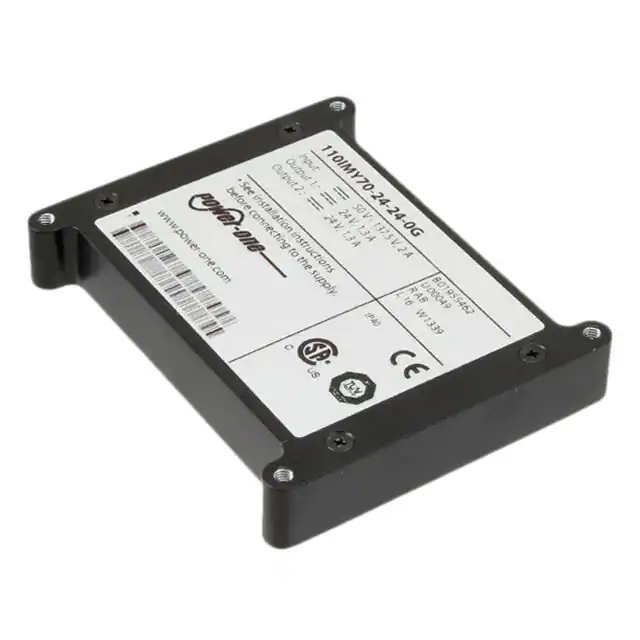
Product Marking
Converters without option Z are marked with the type designation, input and output voltages and currents, applicable safety
approval and recognition marks, company logo, date code, and serial no.
tech.support@psbel.com
belfuse.com/power-solutions
BCD.00002 Rev AJ, 28-May-2018
© 2018 Bel Power Solutions & Protection
Page 2 of 17
�IMX70 / IMY70 Series
70 to 90 Watt DC-DC Converters
Functional Description
The IMX/IMY70 Series converters are comprised of a feedback-controlled forward converter using current-mode pulse width modulation
(PWM). The switching frequency is fixed; it can by externally synchronized for double-output models. The main transformer and the
output choke are designed in planar technology, which guarantees excellent mechanical features and reproducibility of electric properties.
No optocouplers are used.
Single-output converters exhibit at the output a synchronous rectifier and sense lines to ensure accurate output voltage regulation. An
auxiliary input R allows adjustment of the output voltage. Proper parallel operation is possible using the current sharing feature.
Double-output converters exhibit Schottky diodes at both outputs. The first output voltage is sensed and accurately regulated by
influencing the PWM via the magnetic feedback.
The output voltage is transferred to the primary side by magnetic feedback via a pulse transformer. The 2nd output is tracking. The close
magnetic coupling of the main transformer and the main choke guarantee minor deviation of both output voltages. Both outputs can be
simultaneously adjusted by the R input located on the secondary side.
A current limitation circuits limits the possible output power. The topology allows for single-output models an unlimited output capacity
and for double-output models a high output capacity; see Electrical Output Data.
An incorporated protection disables the converter in an overtemperature condition. The converter automatically recovers, after the
temperature has dropped below the limit.
The input voltage is monitored, shutting down the converter in an overvoltage condition. The minimum input voltage for startup can be
externally adjusted, which helps to limit the input current at low input voltage.
n.c.1
1
8
6
8
5
Vi+ 4
Secondary
control circuit
Isolation
Opt. i
Vi+
11 T
Primary
control circuit
8
2
JM027c
1 kΩ
Ref 7
SD
PUL
19
19 R
Synchr. rect.
drive
13 S+
NTC
16
Input
filter
Vi– 2
14
15
Auxiliary
converter
350 kHz
Vi– 2 3
Vo+
17
Cy
Vo–
13 S–
18
Cy
12
1
Not connected
2
n.c.1
Connected for 24IMX models only
Fig. 1
Block diagram of single-output models
SD
W
1
8
6
8
1 kΩ
11 n.c.1
Primary
control circuit
8
Opt. i
Vi+ 2 5
Vi+
4
Vi–
2
JM026c
Secondary
control circuit
Isolation
Ref 7
PUL
19 R
19
PTC
13 Vo2+
14 Vo2–
Input
filter
16 Vo1+
Vi– 2 3
15 Vo1–
Cy
1
Not connected
2
Cy
Connected for 24IMX models only
18
17
12
n.c.1
n.c.1
n.c.1
Fig. 2
Block diagram of double-output models
tech.support@psbel.com
belfuse.com/power-solutions
BCD.00002 Rev AJ, 28-May-2018
© 2018 Bel Power Solutions & Protection
Page 3 of 17
�IMX70 / IMY70 Series
70 to 90 Watt DC-DC Converters
Electrical Input Data
General conditions:
- TA = 25 °C, shutdown and R pin left open-circuit, unless specified.
Table 2: Input data
Model
24IMX70
Characteristics
Conditions
min
max
min
33.6
50
typ
Unit
max
Vi
Operating input voltage
Vi nom
Nominal input voltage
Vi 2s
Temporary input voltage
For 2 s, no shutdown
Vi sur
Repetitive surge voltage
Shutdown, no damage
50
Worst case condition at
Vi min and full load
500
500
500
25
25
TA min to TA max, Io = 0 – Io nom
Switch on
tstart-up
Converter
start-up time
trise
Rise time
Vi = 0 → Vi nom, Io nom
SD high
15
typ
110IMY70
1
137.5
24
12 1
(72, 96), 110
40.1
43.2 1
VDC
154
168
250
200
25
500
ms
Ii o
No-load input current
Io = 0, Vi min – Vi max
Iirr
Reflected ripple current
Io = 0 – Io nom
Iinr p
Inrush peak current
Vi = Vi max
25
35
A
Ci
Input capacitance
For surge calculation
24
7.7
µF
VSD
Shutdown voltage
I SD
Shutdown pin current
Ii SD
Input current at shutdown
Vi min – Vi max
fs
Switching frequency
Vi min – Vi max, Io = 0 – Io nom
30
50
mA
200
mApp
Converter disabled
– 0.7 to +0.7
– 0.7 to +0.7
Converter operating
2 to 20 (or open-circuit)
2 to 20 (or open-circuit)
– 0.2
– 0.2
2
200 2
V
mA
2
210 2
200 2
210 2
kHz
Vi min will not be as stated, if Vo is increased above Vo nom by use of R-input. If the output voltage is set to a higher value, Vi min will be
proportionately increased.
2
Typ. 240 kHz for single-output models, typ. 300 kHz for models with 5 V output
1
Inrush Current
The inrush current has been kept as low as possible by choosing a very small input capacitance. A series resistor may be installed
in the input line, in order to further reduce this current.
A
JM028
Vo
40
trise
Vo nom
30
04008b
20
10
0
20
40
60 µs
t
Fig. 3
Inrush current at Vi nom, Po nom versus time (110IMY70-24-24-8).
Source impedance according to ETS 300132-2: L = 10 μH,
R = 1.5 Ω.
t
tstartup
Fig. 4
Converter start-up and rise time
tech.support@psbel.com
belfuse.com/power-solutions
BCD.00002 Rev AJ, 28-May-2018
© 2018 Bel Power Solutions & Protection
Page 4 of 17
�IMX70 / IMY70 Series
70 to 90 Watt DC-DC Converters
Reverse Polarity Protection and Fuse
The built-in suppressor diode also provides for reverse polarity protection at the input by conducting current in the reverse
direction. An external fuse is required to limit this current.
Table 3: Recommended external fuses in the non-earthed input line
Converter model
Fuse type
Rating
24IMX70 single-output
Littlefuse 166
10 A, 80 V
24IMX70 double-output
Littlefuse 166
10 A, 80 V
110IMY70 single-output
Littlefuse 372
3.15 A, 250 V
110IMY70 double-output
Littlefuse 372
3.15 A, 250 V
Input Transients Protection
When Vi exceeds 154 V, the converter is temporarily disabled. Furthermore, a built-in suppressor diode provides effective protection
against higher input transients, which may be generated for example by short-circuits across the input lines.
Table 4: Built-in transient voltage suppressor
Model
Breakdown voltage
VBr nom [V]
Peak power at 1 ms
Pp [kW]
Peak pulse current
Ipp [A]
24IMX70
56
1.5
19.4
110IMY70
176
0.6
2.5
For very high energy transients as for example to achieve IEC/EN 61000-4-5 compliance (as per table Electromagnetic Immunity)
an external inductor and capacitor are required. The components should have similar characteristics as listed in table below.
Table 5: Components for external circuitry to comply with IEC/EN 61000-4-5; see table 10
Model
Inductor (L)
Capacitor (C)
24IMX70
---
330 μF / 100 V
110IMY70
---
150 μF / 200 V
JM029
L
Vi+
C
+
Vi–
Fig. 5
Example for external circuitry to comply with IEC/EN 61000-4-5; see table 10
tech.support@psbel.com
belfuse.com/power-solutions
BCD.00002 Rev AJ, 28-May-2018
© 2018 Bel Power Solutions & Protection
Page 5 of 17
�IMX70 / IMY70 Series
70 to 90 Watt DC-DC Converters
Electrical Output Data
General conditions:
- TA = 25 °C, unless TC is specified
- Shutdown pin not connected
- R-pin not connected
Table 6: Output data for single-output models
Output
5.1 V
Characteristics
Output voltage
Vo
24IMX
min
typ
max
min
typ
max
Vi nom, 0.5 I o nom
5.07
5.1
5.13
11.94
12.0
12.06
Output current
Io L
Current limit
ΔVo
Line / load regulation
Vnoise
Output voltage noise
V o OS
Output overshot at turn-on
Vi min – Vi max
Vo L
Output overvoltage limit
Min. load 1%
C o ext
Capacitive load
Vo d
24IMX
1
110IMY
3
4
5
7.5
Vi nom, TC = 25 °C
Vo = 93% Vo nom
13.6
13.9
14.4
Vi min – Vi max
(0.1 – 1) I o nom
7.5
8.0
8.5
8.5
8.8
9.2
±0.5
±0.5
Vi min – Vi max
2
100
150
I o = I o nom
3
50
80
0.1
6.0
15
%
mVpp
V
unlimited
μF
±1800
mV
2
I o = (0.1 to 1) I o nom
13.5
A
unlimited
±1000
Vi min – Vi max
0.24
7.0
or (0.1 ↔ 0.6) I o nom
Temperature coefficient ΔVo / ΔTC
2
12
Vi nom, (0 ↔ 0.5) I o nom
a Vo
1
Vi min – Vi max
Recovery time
Dynamic load
regulation
V
7.0
Voltage deviation
td
Unit
Conditions
Io nom
110IMY
12 V
4
5
2
±0.02
ms
±0.02
%/K
Rectangular characteristic Vo /Io
BW = 20 MHz, measured with an external capacitor of 1 µF across each pair of output pins.
Measured with a probe according to EN 61204
With an output cap Co = 2200 µF: ±250 mV
With an output cap Co = 1500 µF: ±600 mV
tech.support@psbel.com
belfuse.com/power-solutions
BCD.00002 Rev AJ, 28-May-2018
© 2018 Bel Power Solutions & Protection
Page 6 of 17
�IMX70 / IMY70 Series
70 to 90 Watt DC-DC Converters
Table 7: Output data for single- and double-output models; general condition as per table 6.
Output
15 V
Characteristics
Conditions
Vo
Output voltage
Io nom
Output current
Vi nom, 0.5 I o nom
24IMX
24IMX
Current limit 1
Io L
110IMY
typ
max
14.93
15.0
15.08
23.88
24.0
24.12
2 x 1.3
Vi nom, TC = 25 °C
3.0
3.15
3.3
Vo = 93% Vo nom
6.6
7.5
3.0
3.15
3.3
Vi min – Vi max
V o OS
Output overshot at turn-on
Vi min – Vi max
Vo L
Output overvoltage limit
Min. load 1%
C o ext
Capacitive load
V
2 x 1.3
7.0
Output voltage noise
a Vo
min
6.2
Vnoise
Dynamic load
regulation
max
6.0
Line / load regulation
td
typ
5.7
ΔVo
Vo d
Unit
min
Vi min – Vi max
110IMY
2 x 24 V
(0.1 – 1) I o nom
±0.5
±0.5
Vi min – Vi max
2
150
200
I o = I o nom
3
100
150
0.3
16.8
A
%
mVpp
0.48
18
V
4
unlimited
0
1500 6, 7
μF
Voltage deviation
Vi nom, (0 ↔ 0.5) I o nom
±1500 5
±1500
mV
Recovery time
or (0.1 ↔ 0.6) I o nom
2
2
ms
Temperature coefficient ΔVo / ΔTC
Vi min – Vi max
±0.02
I o = (0.1 to 1) I o nom
±0.02
%/K
The current limit is primary side controlled. In an overload condition the thermal protection may cause the converter to shut down
(automatic restart on cool-down).
2
BW = 20 MHz, measured with an external capacitor of 1 µF across each output pins.
3
Measured with a probe according to EN 61204
4
Both outputs of double-output models are protected by a suppressor diode.
5
With an output cap Co = 1500 µF: ±750 mV
6
Both outputs of double-output models connected in parallel. For series connection, only 1/4 of the capacitance is possible.
7
1000 µF for 110IMY70-24-24 produced before 2012
1
Thermal Considerations
Fig. 6a and 6b specify the admissible output power of a converter, mounted on a printed circuit board, located in free environment,
exposed to an airflow with the ambient temperature TA. This applies to continuous operation in the input voltage range Vi min to
Vi max; see table 2, Input data. The case temperature TC (TC Z for option Z) measured at the measuring point of case temperature
(see Mechanical Data) will approach the indicated value TC max after the warm-up phase.
However, the reached temperature TC depends heavily on the conditions of operation, the distance and temperature of surrounding
components, the orientation of the converter and the airflow, and the surfaces, thickness, and properties of the printed circuit board.
Caution: The case temperature TC (TC Z for option Z), measured at the temperature measuring point (see Mechanical Data) may under no
circumstances exceed the specified maximum value. The installer must ensure that under all operating conditions TC (TC Z) remain within the
limits stated in the table Temperature specifications.
Io / Io nom
Io / Io nom
1.0
1.0
JM036b
1 m/s = 200 LFM
0.8
natural cooling
0.4
0.2
0
0.5 m/s = 100 LFM
0.6
natural cooling
0.4
1 m/s = 200 LFM
0.8
0.5 m/s = 100 LFM
0.6
JM039b
0.2
20
40
60
80
100
°C
Fig. 6a
Maximum allowed output power versus ambient
temperature for cased models 24IMX70-24-24-0 and
110IMY70-24-24-0 (with rev. AB or greater).
TA
0
20
40
60
80
100
°C
TA
Fig. 6b
Maximum allowed output power versus ambient
temperature for 24IMX70-24-24-0Z and 110IMY70-24-24-0Z
(with rev. AB or greater).
tech.support@psbel.com
belfuse.com/power-solutions
BCD.00002 Rev AJ, 28-May-2018
© 2018 Bel Power Solutions & Protection
Page 7 of 17
�IMX70 / IMY70 Series
70 to 90 Watt DC-DC Converters
Io / Io nom
Io / Io nom
1.0
1.0
JM118
0.8
JM099b
0.8
0.6
0.6
natural cooling
0.4
natural cooling
0.4
0.2
0.2
0
20
40
60
80
100
°C
0
TA
Fig. 6c
Max. allowed output power versus ambient temperature for
converters 110IMY70-12 without opt. Z in vertical position.
20
40
60
80
100
°C
TA
Fig. 6d
Max. allowed output power versus ambient temperature for
converters 110IMY70-12-0Z in vertical position.
Overtemperature Protection
The converter is protected against possible overheating by means of an internal temperature monitoring circuit. It shuts down
the converter above the internal temperature limit and attempts to automatically restart. This feature prevents excessive internal
temperature building up, which could occur under heavy overload conditions.
Short Circuit Behavior
The current limiting circuit decreases the output voltage, when an overcurrent occurs. It protects against a short circuit and
automatically recovers after removal of the overload condition. If one output of double-output models is overloaded, the current
limiting circuit decreases the output voltage of output 1 and simultaneously of the tracking output 2.
Vo
Vo nom
Vo [%]
0.98
100
overload condition
switch-off
05041c
70
0.5
0
JM097
0.5
1.0
IoL
Io
Io nom
Fig. 7
Rectangular current limitation of single-output models
0
0.3 s
t
Fig. 8
Current limitation of double-output models with both outputs
connected in parallel
Connection in Series and in Parallel
The outputs of all models may be connected in series without any precaution. If single-output converters are operated in parallel,
we recommend ordering option T.
Both outputs of a double-output converter can be connected in parallel without precaution and will share their currents evenly.
Note: If output 2 of a double-output converter is not used, connect it in parallel with output 1 !
Single-output converters without option T or double-output converters with the same nominal output voltage should only be
operated in parallel with some precautions. The output lines to the load should have the same length and section. To improve the
current repartition, small resistors should be present in the output lines. If ORing diodes are used, double Schottky diodes should
be chosen to keep both diodes at the same temperature level. If single diodes are chosen, they should be mounted on the same
heat sink. If the total load exceeds 150% of the nominal load of one converter, start-up problems are possible.
Note: Instead of connecting two 24 V models in parallel, we recommend connecting of two 12 V models in series.
tech.support@psbel.com
belfuse.com/power-solutions
BCD.00002 Rev AJ, 28-May-2018
© 2018 Bel Power Solutions & Protection
Page 8 of 17
�IMX70 / IMY70 Series
70 to 90 Watt DC-DC Converters
Cross Regulation of Double-Output Models
See fig. 9. General conditions:
– TA = 25°C, unless TC is specified.
– Shutdown and R pin left open-circuit.
Efficiency
Vo / Vo nom
JM030a
1.1
Vo2
1.05
1.0
Vo1
0.95
0.9
0.85
0
0.2
0.4
0.6 0.8 1.0 1.2 1.4 1.6 1.8 Io / Io nom
Fig. 9
Cross regulation of double-output models (typ.) Vo2 versus Io2, Io1 = 0.5 Io1 nom
η [%]
η [%]
JM096
100
Vi = 15 V
90
80
0
0.2
0.4
0.6
0.8
Io / Io nom
Fig. 10a
Efficiency versus input voltage and load. Typical values
(24IMX70-24-24)
60
0
2
6
4
8
Io / Io nom
Fig. 10b
Efficiency versus input voltage and load. Typical values
(110IMY70-05)
η [%]
η [%]
JM098
100
JM040a
100
Vi = 50 V
Vi = 50 V
90
90
Vi = 110 V
80
Vi = 110 V
80
Vi = 137 V
Vi = 150 V
70
70
60
Vi = 137 V
70
70
60
Vi = 110 V
Vi = 50 V
90
Vi = 24 V
Vi = 33.6 V
80
JM163
100
0
2
4
6
8
Io / Io nom
Fig. 10c
Efficiency versus input voltage and load. Typical values
(110IMY70-12)
60
0
0.2
0.4
0.6
0.8
Io / Io nom
Fig. 10d
Efficiency versus input voltage and load. Typical values
(110IMY70-24-24)
tech.support@psbel.com
belfuse.com/power-solutions
BCD.00002 Rev AJ, 28-May-2018
© 2018 Bel Power Solutions & Protection
Page 9 of 17
�IMX70 / IMY70 Series
70 to 90 Watt DC-DC Converters
Auxiliary Functions
Adjustable Output Voltage
As a standard feature, the converters offer adjustable output voltages by using the control input R. Fig. 11 shows the schematic
diagram of the circuitry. If the control input is left open-circuit, the output voltage is set to Vo nom.
Note: For output voltages Vo > Vo nom, the minimum input voltage Vi min (see Electr. Input Data) increases proportionally to Vo /Vo nom.
06029e
Vi+
Vo+
Vref = 2.5 V
+
Rext2
4 kΩ
R
Control
logic
Vi–
+
Rext1
Vo–
–
Vext
Fig. 11
Output voltage control by means of the R input
The R-input is referenced to the secondary side of the converter. Adjustment of Vo (or Vo1) is possible by means of either an external
resistor or a voltage source.
a) Adjustment by means of an external resistor Rext.
Depending upon the value of the required output voltage, the resistor shall be connected:
either: Between the R-pin and Vo– (or Vo1) to achieve an output voltage adjustment range of Vo ≈ 80 to 100 % of Vo nom
Single-output models can be trimmed to Vo ≈ 0 V.
Vo
__________
Rext1 ≈ 4 kΩ •
Vo nom – Vo
or: Between the R-pin and Vo+ (or Vo1+) to achieve an output voltage range of Vo ≈ 100 to 105% of Vo nom.
(Vo – 2.5 V)
___________________
Rext2 ≈ 4 kΩ •
2.5 V • (Vo /Vo nom – 1)
b) Adjustment by means of an external voltage Vext between Vo– (or Vo1–) and the R-pin.
The control voltage range is 1.96 to 2.62 V and allows for adjustment in the range of Vo ≈ 80 to 105% of Vo nom.
Single-output models can be trimmed to Vo ≈ 0 V.
V • 2.5 V
o
V
≈ __________
ext
Vo nom
Note: Single-output models can be trimmed up to 110% of Vo nom.
Note: Applying a higher external control voltage as needed for the max. trim range may damage the converter.
Reference Output (Ref)
The converter provides a stable 5 V (± 0.25 V) reference signal on pin 7 (Ref). The output is protected by a 1 kΩ resistor.
Note: It is recommended to connect a filter capacitor (0.1 µF) between Ref and Vi–, if Ref is used.
Current Sharing (T)
This feature is available for single-output models. Several parallel connected converters will share their current evenly by
interconnecting the T pins (pin 11).
Note: This feature allows connecting the outputs together through ORing diodes to achieve redundancy. We recommend Schottky diodes
mounted onto the same heat sink (for thermal balancing).
tech.support@psbel.com
belfuse.com/power-solutions
BCD.00002 Rev AJ, 28-May-2018
© 2018 Bel Power Solutions & Protection
Page 10 of 17
�IMX70 / IMY70 Series
70 to 90 Watt DC-DC Converters
Sense Lines
The sense inputs of single-output models allow for compensating a voltage drop up to 1 V (0.6 V for models with Vo nom = 5.1 V).
Synchronization (W)
Double-output models can be synchronized to an external TTL signal (220 ±10 kHz, duty cycle 10 – 15%). Due to the higher
switching frequency, the efficiency will slightly drop.
Note: If this feature is not used, W (pin 6) can be connected to Vi– (pin 2) or left open-circuit.
__
Shutdown (SD )
The outputs of the converters may be enabled or disabled by a logic signal (TTL, CMOS, etc.) applied between the shutdown pin
8 and Vi–. If the shutdown function is not required, pin 8 should be left open-circuit. Voltage on pin 8:
Converter operating:
Converter disabled:
2.0 to 20 V
– 0.7 to +0.7 V
Progr. Input Voltage Lockout PUL
A special feature of these converters is the adjustable undervoltage lockout function, protecting the converter (and system) from
high currents caused by operation at too low input voltage. This ensures easier start-up in distributed power systems.
The undervoltage lockout level can be programmed by an external resistor R PUL (between PUL and Vi –) to increase the preset
levels, as indicated in the table below (with hysteresis). The overvoltage lockout (OVL) cannot be varied.
Table 8: Turn-on and shutdown voltage (pin 1 left open)
Model
Turn-on level
Hysteresis
OVL
24IMX70
3.5 – 14.5
typ. 2.5
41 – 43
110IMY70
44.5 – 47.5
typ. 6
160 – 175
Unit
V
Table 9: Typical values for R PUL and the respective turn-on input voltage Vi LO.
24IMX70
Vi LO [V]
R PUL [kΩ ]
single-output
110IMY70
double-output
Vi LO [V]
R PUL [kΩ ]
single-output
double-output
14
∞
∞
46
∞
∞
16
40.5
120
50
68
270
18
60
62
57
25.5
110
20
65
41
61
18
82
tech.support@psbel.com
belfuse.com/power-solutions
BCD.00002 Rev AJ, 28-May-2018
© 2018 Bel Power Solutions & Protection
Page 11 of 17
�IMX70 / IMY70 Series
70 to 90 Watt DC-DC Converters
Electromagnetic Compatibility (EMC)
A suppressor diode together with an input filter form an effective protection against high input transient voltages which typically
occur in many installations, but especially in battery-driven mobile applications.
Electromagnetic Immunity
Table 10: Electromagnetic immunity (type tests)
Phenomenon
Standard
Level
Coupling mode 1
Value
applied
Electrostatic
discharge
(to case)
IEC/EN
61000-4-2
3
contact discharge
(R pin open)
±6000 Vp
3
air discharge
(R pin open)
±8000 Vp
Electromagnetic
field
IEC/EN
61000-4-3
x4
antenna
20 V/m
Waveform
1/50 ns
AM 80% / 1 kHz
20 V/m
5
antenna
10 V/m
Source
imped.
330 Ω
150 pF
Surges
Conducted
disturbances
1
3
4
5
6
7
8
2
IEC/EN
61000-4-4
36
4
direct coupling
+i/c, – i/c, +i/–i
±2000 Vp
±4000 Vp
3
capacit. coupl.
o/c
±2000 Vp
IEC/EN
61000-4-5
37
+i/c, – i/c
±2000 Vp
27
+i/– i
±1000 Vp
IEC/EN
61000-4-6
38
i, o, signal wires
10 VAC
(140 dBµV)
In
oper.
Perf.
crit. 2
yes
B
yes
A
yes
A
yes
A
yes
B
yes
B
5 pos. & 5 neg.
surges per
coupling mode
yes
B
0.15 – 80 MHz
yes
A
10 pos. & 10 neg.
discharges
N/A
80 – 1000 MHz
N/A
800 – 1000 MHz
AM 80% / 1 kHz
1400 – 2100 MHz
5 V/m
Electrical fast
transients / burst
Test procedure
2100 – 2500 MHz
50 Ω
bursts of 5/50 ns;
5 kHz over 15 ms;
burst period: 300 ms
1.2 / 50 µs
AM 80% / 1 kHz
12 Ω/ 9 μF
2 Ω/ 18 μF
150 Ω
60 s positive
60 s negative
transients per
coupling mode
i = input, o = output, c = case (not for option Z)
A = normal operation, no deviation from specification, B = temporary deviation from specs. possible.
Corresponds to EN 50121-3-2:2016 table 5.3 and EN 50121-4:2016 table 2.4.
Corresponds to EN 50121-3-2:2016 table 5.1 and exceeds EN 50121-4:2016 table 2.1.
Corresponds to EN 50121-3-2:2016 table 5.2 and EN 50121-4:2016 table 2.2.
Corresponds to EN 50121-3-2:2016 table 3.2 and EN 50121-4:2016 table 4.2.
Measured with an external input capacitor specified in table 5. Exceeds EN 50121-3-2:2016 table 3.3 and EN 50121-4:2016 table 4.3.
Corresponds to EN 50121-3-2:2016 table 3.1 and EN 50121-4:2016 table 4.1.
Electromagnetic Emissions
The EMC requirements must be observed at the end product system level. However, we test the converters to EMC standards. An
effective integrated input filter significantly reduces the reflected input current and improves EMC features. Further improvements
are possible by adding external filters.
dbµV
JM251
80
EN 55022 A qp
EN 55022 A avr
60
40
20
0
0.2
0.5
1
2
5
10
20 MHz
Fig. 12
Typical disturbance voltage at the input (green = peak, x = quasi-peak, pink = average) according to EN 55011,
measured at Vi nom and Io nom. Output leads = 0.1 m, twisted (110IMY70-24-24).
tech.support@psbel.com
belfuse.com/power-solutions
BCD.00002 Rev AJ, 28-May-2018
© 2018 Bel Power Solutions & Protection
Page 12 of 17
�IMX70 / IMY70 Series
70 to 90 Watt DC-DC Converters
Immunity to Environmental Conditions
Table 11: Mechanical and climatic stress
Test method
Standard
Test Conditions
Cab
Damp heat
steady state
IEC/EN 60068-2-78
MIL-STD-810D section 507.2
Temperature:
40 °C
Relative humidity:
93 +2/-3 %
Duration:
56 days
Damp heat test,
cyclic
EN 50155:2007, clause 12.2.5
IEC/EN 60068-2-30
Temperature:
55 °C and 25 °C
Cycles (respiration effect):
2
Duration:
2 x 24 h
Db
Bd
Ad
Ka
Fc
Fh
Ea
---
---
1
Status
±2
Converter
not operating
Dry heat test
steady state
EN 50155:2007, clause 12.2.4
IEC/EN 60068-2-2
Temperature:
70 °C
Duration:
6h
Cooling test
steady state
EN 50155:2007, clause 12.2.3
IEC/EN 60068-2-1
Temperature, duration:
-40 °C, 2 h
Performance test:
+25 °C
Salt mist test
sodium chloride
(NaCl) solution 2
EN 50155:2007, clause 12.2.10
IEC/EN 60068-2-11
class ST2
Temperature:
35 ±2 °C
Duration:
16 h
Vibration
(sinusoidal)
IEC/EN 60068-2-6
MIL-STD-810D section 514.3
Acceleration amplitude:
0.35 mm (10 – 60 Hz)
Random vibration
broad band (digital
control) & guidance
IEC/EN 60068-2-64
Shock
(half-sinusoidal)
IEC/EN 60068-2-27
MIL-STD-810D section 516.3
Shock
Simulated long life
testing at increased
random vibration
levels
Converter
not operating
Converter
operating
Converter
not operating
Converter
not operating
5 gn = 49 m/s2 (60 - 2000 Hz)
Frequency (1 Oct/min):
10 – 2000 Hz
Test duration:
7.5 h (2.5 h in each axis)
Acceleration spectral density:
0.05 gn2/Hz
Frequency band:
8 – 500 Hz
Acceleration magnitude:
4.9 gn rms
Converter
operating
Converter
operating
Test duration:
1.5 h (5 h in each axis)
Acceleration amplitude:
50 gn = 490 m/s2
Bump duration:
11 ms
Number of bumps:
18 (3 in each direction)
EN 50155:2007, clause 12.2.11
EN 61373 sect. 10
class B, body mounted 1
Acceleration amplitude:
5.1 gn
Bump duration:
30 ms
Number of bumps:
18 (3 in each direction)
EN 50155:2007, clause 12.2.11
EN 61373 sect. 8 and 9
class B, body mounted 1
Acceleration spectral density:
0.02 g n2/Hz
Frequency band:
5 – 150 Hz
Acceleration magnitude:
0.8 g n r ms
Test duration:
15 h (5 h in each axis)
Converter
operating
Converter
operating
Converter
operating
Body mounted = chassis of a railway coach
Models with option Z have been covered by lacquer (AVR80 or Peters SL1301) in order to simulate the end-use situation.
2
Temperatures
Table 8: Temperature specifications, valid for an air pressure of 800 – 1200 hPa (800 – 1200 mbar)
Model
-0
Characteristics
TA
Ambient temperature
TC
Case temperature (without opt. Z) 2
TC Z
Component temperature with opt. Z
TS
Storage temperature
Conditions
min
In operation 1
- 40
100 1
- 40
105 2
- 40
115 2
- 55
85
2
Not operational
typ
Unit
max
°C
See Thermal Considerations
2
Temperature measurement point; see Mechanical Data
1
tech.support@psbel.com
belfuse.com/power-solutions
BCD.00002 Rev AJ, 28-May-2018
© 2018 Bel Power Solutions & Protection
Page 13 of 17
�IMX70 / IMY70 Series
70 to 90 Watt DC-DC Converters
Reliability
Table 13: Calculated MTBF at nominal load
Model
Ground benign
Ground fixed
Ground mobile
40 °C
40 °C
70 °C
50 °C
(Bellcore Telc. SR-332)
1 022 000
510 000
162 500
118 500
110IMY70-05
(Bellcore Telc. SR-332)
720 000
360 000
98 000
98 000
110IMY70-12
(Bellcore Telc. SR-332)
825 000
413 000
182 000
106 000
110IMY70-24-24
(Bellcore Telc. SR-332)
1 000 000
632 000
163 000
117 400
24IMX70-24-24
1
Device hours
Unit
h
with an air flow of 0.5 m/s
Mechanical Data
Dimensions are in mm. Tolerances ±0.3 mm (unless noted).
European
Projection
4 threads M3
JM032a
TC
Tc
0.8 x 0.8
47.8
5.08
56.9
Bottom
view
63.5
0.8 x 0.8
5.08
1
JM031
Bottom
view
19
63.5
63.5
69.6
72.8
76.2
Fig. 13
Case IMX70/IMY70 (without opt. Z)
Material Zinc; weight: approx. 140 g
Cores
Components
100
>100
---
---
MΩ
Insulation resistance at 500 VDC
For open-frame models (option Z), only the insulation input to outputs is tested.
1.5 kVAC according to IEC 60950, sect. 6.2, Telecom equipment; type test with 1.5 kVAC / 60 s (IEE 802.3).
3
The test voltage between outputs is not applied as routine test.
1
2
tech.support@psbel.com
belfuse.com/power-solutions
BCD.00002 Rev AJ, 28-May-2018
© 2018 Bel Power Solutions & Protection
Page 16 of 17
�IMX70 / IMY70 Series
70 to 90 Watt DC-DC Converters
Options
Option i: Inhibit (Negative Shutdown Logic)
The output of the converter may be enabled or disabled by means of a logic signal (TTL, CMOS, etc.) applied to the inhibit pin 8.
06138a
4 Vi+
8 i
2 Vi –
Fig. 17
If the inhibit function is not used, connect the inhibit pin i with Vi–.
No output voltage overshoot will occur, when the converter is turned on. If the inhibit function is not required the inhibit pin 8 should
be connected to Vi– to enable the output (active low logic, fail safe). Voltage on pin 8:
Converter operating:
Converter disabled:
–10 V to +0.8 V
2.4 V to 20 V
Option Z
If the converters are mounted onto a mother board, in many cases, a converter case is not required. Only converters with option
Z are not varnished, and this allows dipping of the populated board including the converter into a protection lacquer.
Note: The converters shall not be exposed to cleaning processes, as this will damage the glue of the ferrite cores.
NUCLEAR AND MEDICAL APPLICATIONS - These products are not designed or intended for use as critical components in life support systems,
equipment used in hazardous environments, or nuclear control systems.
TECHNICAL REVISIONS - The appearance of products, including safety agency certifications pictured on labels, may change depending on the
date manufactured. Specifications are subject to change without notice.
tech.support@psbel.com
belfuse.com/power-solutions
BCD.00002 Rev AJ, 28-May-2018
© 2018 Bel Power Solutions & Protection
Page 17 of 17
�