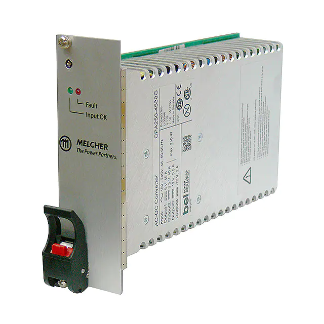
Compact PCI®
CPA / CPD Series
200 – 550 Watt AC-DC and DC-DC Converters
Features
•
•
•
•
•
•
•
•
•
•
•
•
Compliant to PICMG® CompactPCI® specifications
Wide range DC or AC input with PFC
Extremely high efficiency and high power density
Low inrush current
4 high current outputs with flexible load distribution
Integrated ORing FETs / diodes for true redundancy
Inhibit and enable inputs
Remote sense lines
Single-wire current share function for 3 outputs
Hot-swap capability
47 pin connector, type Positronic
Overtemperature, overvoltage, overcurrent, and
overpower protection
Safety-approved to the latest edition of UL/CSA 60950-1
and IEC/EN 62368-1.
233.3
7.8"
6U
100
3.94"
3U
40.4
1.6"
162.5
6.4"
Table of Contents
40.6
1.6"
8 HP
162.5
6.4"
Description........................................................................................2
Model Selection.................................................................................2
Functional Description.......................................................................3
Electrical Input Data..........................................................................5
Electrical Output Data.......................................................................7
Auxiliary Functions.......................................................................... 11
Electromagnetic Compatibility (EMC)..............................................14
Immunity to Environmental Conditions............................................17
Mechanical Data..............................................................................18
Safety and Installation Instructions..................................................19
Description of Options.....................................................................21
belfuse.com/power-solutions
BCD20005-G_AP2, 9 January 2024
�Compact PCI® CPA/CPD Series
200 – 550 Watt AC-DC and DC-DC Converters
Description
The CPA and CPD Series are highly reliable power supplies for CompactPCI® systems, which are increasingly used in communications,
industrial, military, aerospace, and other applications. These power supplies offer high power density in plug-in modules that meet the
requirements of the PICMG® power interface specification for CompactPCI® systems.
The converters use the patented EDGETM technology and provide important advantages such as flexible output power, extremely high
efficiency, excellent reliability, full input-to-output isolation, negligible inrush current, hot-swap capability, soft start, and overtemperature
protection.
The input is protected by a transient suppressor (varistor) against surges and transients occurring on the source lines and cover an
operating input voltage range from either 90 to 264 VAC or 36 to 75 VDC.
The outputs are protected against continuous overload, open-circuit, and short-circuit. Full n+1 redundant operating mode is made
possible by integrated ORing FETs or ORing diodes. When several converters are connected in parallel, a single-wire connection
between converters ensures proper current sharing.
The converters are designed with two or three separate forward converters with fixed switching frequency and synchronous rectifiers
at their output.
LEDs on the front panel and various warning signals display the status of the converter. The aluminum case acts as a heat sink and
as an RFI shield. It is designed for vertical insertion into 19” rack systems, but it can also be mounted in any other position, as long
as the necessary airflow is ensured. The connector is a 47 pin type from Positronic or similar.
Several options are available to meet different requirements.
Model Selection
Table 1: Model selection
Model 4
Output
No.
Operating Input Range
Rated Power 1
Efficiency 2
Vi min – Vi max
Case
Options
Po nom
[W]
min
[%]
typ
[%]
200
80
83.2
3U x 8HP
-
250
80
81.7
3U x 8HP
L, A, C
Vo nom
[V]
Io nom
[A]
Io max
[A]
CPD200-4530G
Vo1
Vo2
Vo3
Vo4
5.0
3.3
12
-12
20
20
2.5
0.5
40
40
5.5
2
CPD250-4530G
Vo1
Vo2
Vo3
Vo4
5.0
3.3
12
-12
25
20
4
1
40
40
5.5
2
CPD500-4530G
Vo1
Vo2
Vo3
Vo4
5.0
3.3
12
-12
40
50
8
3
50
60
12
4
500
83
84.5
6U x 8HP
C
CPA200-4530G
Vo1
Vo2
Vo3
Vo4
5.0
3.3
12
-12
20
20
2.5
0.5
40
40
5.5
2
200
81.5
83.7
3U x 8HP
-
CPA250-4530G
Vo1
Vo2
Vo3
Vo4
5.0
3.3
12
-12
25
20
4
1
40
40
5.5
2
250
81.5
83.2
3U x 8HP
L, A, C
CPA500-4530G
Vo1
Vo2
Vo3
Vo4
5.0
3.3
12
-12
40
50
8
3
50
60
12
4
500
83
85
6U x 8HP
L, A, F, C
CPA550-4530G
Vo1
Vo2
Vo3
Vo4
5.0
3.3
12
-12
50
50
8
3
50
60
12
4
550
83
84.7
6U x 8HP
-
3
4
1
2
fi min – fi max
36...(48)...75 VDC
90...(230)...264 VAC
47 – 63 Hz 3
The sum of the power of all outputs may not exceed the total power for the specified required forced-air cooling.
Efficiency at TA = 25 °C, Vi nom, I o nom.
Rated input voltage range is 100 – 240 VAC, rated input frequency range is 50 – 60 Hz.
RoHS is standard, with G suffix at the end of the part number.
NFND: Not for new designs.
Note: The sequence of options in the model designation must follow the order above. G is always placed at the end.
tech.support@psbel.com
belfuse.com/power-solutions
BCD20005-G_AP2, 9 January 2024
© 2024 Bel Fuse Inc.
Page 2 of 21
�Compact PCI® CPA/CPD Series
200 – 550 Watt AC-DC and DC-DC Converters
Product Marking
Label with specific type designation, applicable safety approvals and recognition marks, CE mark, warnings, patents, company
logo, input voltage range, nominal output voltages and output currents, degree of protection, batch no., serial no., and data code
including production site, modification status, and date of production. Identification of LEDs on the front panel.
Functional Description
The inputs of all converters are protected against surges and transients occurring on the source lines. A highly efficient input filter
and an active inrush current limiter ensure a very low inrush current of short duration. This prevents circuit breakers and fuses
from tripping at switch-on.
All CPA models have an additional bridge rectifier and a boost converter to provide active power factor correction (PFC) according
to EN 61000-3-2.
The CPx200/250 models (see fig.1a) are equipped with two independent high efficient 2-switch forward converters, switching 180°
out of phase to minimize the ripple current at the input.
On the secondary side, two high-current synchronous rectifiers supply Vo1 (5 V) and Vo2 (3.3 V) with up to 40 A. The secondarycontrolled Vo3 (+12 V) post regulator is supplied by an additional winding of the 3.3 V main transformer. The linear regulator for
Vo4 (–12 V) is supplied from the output choke of the Vo3 output. The output filters reduce ripple and noise to a minimum without
compromising the dynamic response.
The models CPD500 (fig. 1b) and CPA500/550 (fig. 1c) exhibit a third forward converter for both outputs Vo3 and Vo4. The outputs
Vo1 an Vo2 provide up to 50 and 60 A.
All outputs are fully regulated and protected from the bus by decoupling FETs or diodes. A current monitor calculates the output
power. As soon as the output power exceeds the maximum threshold level, the converter starts to reduce the output power by
decreasing the output voltages.
In contrast to the outputs Vo1 (5 V), Vo2 (3.3 V), and Vo3 (+12 V) with active current sharing, output Vo4 (–12 V) has a droop
characteristic for passive current sharing.
If for some reason the voltage of any output exceeds the nominal value significantly, the converter is permanently shut down. If
option L is fitted, this occurs as well, if the max. output current is exceeded for a predefined time. To reset, the input voltage must
be removed for a short time.
Melcher’s Efficient Dual Geometric Edge Technology (EDGE TM) facilitates high current density, increases reliability by reducing
component stresses, and decreases the amount of heat dissipated. The backbone of this patented technology is an interleaved,
multi-channel forward converter utilising a transitional resonant switching technique and proprietary leading and trailing-edge
pulse-width modulation. It has a proven track record in high-availability power solutions.
RTN
(22)
INH#
39
EN#
27
1 Only
Secondary
control
circuit
Primary
control
circuit
Vo1
Secondary
control
circuit
45
CY
ORing
FET
ORing
FET
Vo2
ORing
FET
Vo3
ORing
diode
Vo4
+
Cb
Primary
control
circuit
CY
Inrush
current
limiter
+
+
Secondary
control
circuit
Bridge
rectifier1
Input filter
Fuse
ACL
–DCIN
47
CY
Forward
converter
≈135 kHz
Forward
converter
≈135 kHz
+
CY
+
Inhibit
logic
CY
CPA models have a bridge rectifier and a boost converter
Linear
regulator
+
ACN
+DCIN
46
Boost converter ≈135 kHz1
03110f
+
+
–
+
Cy
Fig. 1a
Block diagram of CPA/CPD200 and CPA/CPD250 models. For the pin allocation, see Mechanical Data.
tech.support@psbel.com
belfuse.com/power-solutions
BCD20005-G_AP2, 9 January 2024
© 2024 Bel Fuse Inc.
Page 3 of 21
�Compact PCI® CPA/CPD Series
200 – 550 Watt AC-DC and DC-DC Converters
The switching frequency is typically 135 kHz. Recent models (CPD200/250 version V119 or later, CPA200/250 version V117 or later,
CPA500/550 version V110 or later, not CPD500) exhibit a crystal oscillator with 131 kHz.
All models have a separate auxiliary supply for the primary circuits, the CPD500 as well for the secondary circuits. The secondary
bias voltage of the other models is generated by the forward converters. Only the forward converters are controlled by the inhibit
and enable inputs; see Auxiliary Functions.
+DCIN
46
+
CY
+
CY
Secondary
control
circuit
Forward
converter
≈135 kHz
CY
Secondary
control
circuit
VSBias
ORing
FET
Vo2
Secondary
control
circuit
+
ORing
FET
Vo3
Secondary
control
circuit
Forward
converter
≈135 kHz
Vo1
ORing
diode
Vo4
Secondary
control
circuit
Inhibit
logic
CY
ORing
FET
ORing
FET
Vo1
Secondary
control
circuit
Primary
control
circuit
Primary
control
circuit
Auxiliary
converter
+
ORing
FET
Vo2
Secondary
control
circuit
VPBias
RTN
(22)
INH#
39
EN#
27
Cb
Forward
converter
≈135 kHz
ORing
FET
Vo3
Secondary
control
circuit
45
+
Primary
control
circuit
CY
Dual interleaved boost
converter ≈105 kHz
VDR
Input filter
Fuse
–DCIN
47
CY
Inrush current limiter with
reverse polarity protecton
JM041a
Vi
ORing
diode
Vo4
+
+
+
–
+
Fig. 1b
Block diagram of CPD500 models. For the pin allocation, see Mechanical Data.
JM014b
RTN
(22)
INH#
39
EN#
27
Inrush
current
limiter
CY
VPBias
Inhibit
logic
Auxiliary
converter
Primary
control
circuit
45
Bridge
rectifier
Fuse
ACL
47
Input filter
CY
Cb +
Primary
control
circuit
Vi
Primary
control
circuit
2nd fuse
(option F)
Boost converter ≈135 kHz
ACN
46
Forward
converter
≈135 kHz
+
CY
Forward
converter
≈135 kHz
+
CY
Forward
converter
≈135 kHz
+
VSBias
+
+
+
CY
+
CY
–
+
Fig. 1c
Block diagram of CPA500/550 models. For the pin allocation, see Mechanical Data.
tech.support@psbel.com
belfuse.com/power-solutions
BCD20005-G_AP2, 9 January 2024
© 2024 Bel Fuse Inc.
Page 4 of 21
�Compact PCI® CPA/CPD Series
200 – 550 Watt AC-DC and DC-DC Converters
Electrical Input Data
General Conditions:
TA = 25 °C, unless TC is specified.
Table 2a: Input data of CPD models
Model
Characteristics
CPD200/250
Conditions
min
36
typ
CPD500
max
min
75
36
80
0
Vi
Operating input voltage
Io = 0 – Io nom
Vi nom
Nominal input voltage
TC min – TC max
Vi abs
Input voltage limits
≤60 s, no damage
Ii
Typical input current
Vi nom, I o nom
5.1 / 6.3 2
Ii max
Max input current
Vi min, I o nom
7.0 / 8.7 2
Iinr p
Peak inrush current
Vi nom, I o nom
Pi 0
No-load input power
Vi min, Io = 0
Vi nom, Io = 0
Vi max, Io = 0
P i inh
Input power when inhibited
Vi min – Vi max
Ci
Input capacitance
fswitch
Switching frequency
Vi nom, I o nom
th
Hold-up time
Vi min → 0 V, Io nom
4
5
tbo
Brown-out time 4
Vi nom, I o nom
4
5
tsu
Start-up time
Vi nom, I o nom
48
typ
Unit
max
75
48
0
VDC
80
12.5
7.6 / 9.5 2
17
12
14
18
27
17.5
A
25
28.6
28
27.5
30
3.2
31
W
9.4
1360
15
µF
135
135
kHz
150
ms
200
1500
Table 2b: Input data of CPA models
Model
Characteristics
CPA200/250
Conditions
min
typ
Vi
Rated input voltage range
Io = 0 – Io nom
100
Vi op
Operating input voltage
TC min – TC max
90
Vi nom
Nominal input voltage
50 - 60 Hz 1
Vi abs
Input voltage limits
≤60 s, no damage
Ii
Typical input current
Vi nom, I o nom
1.1 / 1.4 2
Ii max
Max input current
Vi min, I o nom
2.9 / 3.6 2
Iinr p
Peak inrush current
Vi nom, I o nom
Pi 0
No-load input power
Vi min – Vi max, Io = 0
P i inh
Input power when inhibited
Vi min – Vi max
Ci
Input capacitance
fswitch
Switching frequency
Vi nom, I o nom
th
Hold-up time
Vi min → 0 V, Io nom
tbo
Brown-out time 4
Vi nom, I o nom
tsu
Start-up time
Vi nom, I o nom
Power factor
Vi nom, I o nom
1
2
3
4
CPA500/550
max
min
240
100
264
90
230
0
typ
max
240
264
230
280
0
VAC 1
280
2.8 / 3.1 3
3.2 / 4.0 2
7.1 / 7.8 3
15
23
Unit
A
20
30
26
3.2
32
3.2
W
1
4
µF
135
135
kHz
20
20
ms
150
0.95
150
0.95
W/VA
Rated input frequency: 50 – 60 Hz, operating input frequency range: 47 – 63 Hz
First value for CPD/CPA200, 2nd value for CPD/CPA250
First value for CPA500, 2nd value for CPA550
Short interruption of Vi without affecting the outputs (EN 61000-4-11)
tech.support@psbel.com
belfuse.com/power-solutions
BCD20005-G_AP2, 9 January 2024
© 2024 Bel Fuse Inc.
Page 5 of 21
�Compact PCI® CPA/CPD Series
200 – 550 Watt AC-DC and DC-DC Converters
Input Fuse and Reverse Polarity Protection
A metal oxide varistor (voltage dependent resistor VDR) together with the input filter form an effective protection against high input
voltage transients, which typically occur in most installations.
An incorporated fuse protects the converter against further damage in the case of a failure.
Note: The fuse is not customer-accessible.
Table 3: Fuse specification
Model
Fuse rating
Reference
CDP200/250
250 V, 12.5 A T
Schurter SPT 5x20, 0001.2515
CPA200/250
250 V, 5 A T
Schurter SPT 5x20, 0001.2511
CPD500
80 V, 25 A F
Littlefuse FKS, 166.7000.525
CPA500/550
250 V, 10 A T
Schurter MXT250, 0034.6925
To avoid unwanted power losses, the CPD200/250 models are not protected against reverse polarity at the input by a serial diode, but
only with an antiparallel diode. In the case of reversed input voltage, the input fuse will blow; however no further damage will occur.
The CPD500 models are protected against reverse polarity by a special circuitry, which generates no losses. The converter will
simply not start-up, but no damage will occur.
The CPA Series converters are designed for AC input and have a rectifier bridge on the input.
Input Current Limitation
All converters incorporate an active inrush current limiter in the input circuitry, which reduces the peak inrush current value by a
factor of 10 – 15 to protect connectors and switching devices from damage.
Note: The inrush current limitation is achieved using electronic circuitry. For effective limitation the converter should not be switched on and
off more frequently than every 8 seconds.
Input Undervoltage Shutdown
CPD200/250 models start at approx. Vi = 22 V, when the input voltage is applied; at decreasing Vi, they switch off at approx. 21 V.
Note: The input current I i may exceed I i max, if Vi ≤ Vi min.
CPD500 models start at Vi = 35 V and switch off at Vi = 33 V.
CPA models exhibit an undervoltage trigger controlling start-up and shutdown. The threshold is between 80 and 90 VAC. See also
Power Fail Signal.
Note: CPA200/250 with version ≤ V116 should not be operated at Vi ≤Vi min, as these models have no undervoltage shutdown and will therefore
operate with a high input current at full load.
Efficiency
The efficiency is specified in table 1. Its dependence upon the input voltage Vi is shown in fig. 2a (CPA models) and fig. 2b (CPD500
models). The efficiency of CPD200/250 models depends only marginally upon Vi.
η [%]
90
η [%]
CPA500/550
JM042
JM018a
86
86
85
CPD500
82
84
CPA200/250
78
0
50
100
150
200
Fig. 2a
CPA Series: Efficiency versus input voltage
250
VAC
83
40
50
60
70
V
Fig. 2b
CPD500 Series: Efficiency versus input voltage
tech.support@psbel.com
belfuse.com/power-solutions
BCD20005-G_AP2, 9 January 2024
© 2024 Bel Fuse Inc.
Page 6 of 21
�Compact PCI® CPA/CPD Series
200 – 550 Watt AC-DC and DC-DC Converters
Electrical Output Data
General Conditions for table 4:
– TA = 25 °C, unless Tc is specified.
– CPD/CPA200: 250 LFM (1.25 m/s), CPD/CPA250: 400 LFM (2 m/s)
– Sense lines connected directly at the connector
Table 4a: Output data of CPD/CPA200 and CPD/CPA250
Vo1 (5.0 V)
Output
Characteristics
Conditions
Vo
Output voltage
Io nom
Nominal output current
Io max
Max. output current
IoL
Output current limit
Io min
Minimum load
Vo
Output voltage
noise 4
∆VoV
Static line regulation
∆VoL
Static load regulation
∆VoS
Overshoot at switch on/off
Vo d
td
α Vo
Dynamic load
regulation
V i nom, 50% Io nom
max
min
typ
max
4.95
5.0
5.05
3.25
3.3
3.35
20 / 25 1
A
50
no min. load required
no min. load required
20
20
Total
45
Temperature coefficient of
output voltage
40
50
BW = 20 MHz 4
Cext = 22 μF + 100 nF
60
40
60
Vi min – Vi max, Io nom
±10
±10
V i nom, 50 - 100% Io max
±10
±10
0
Vo2: ∆Io2 = 10 A, dIo2/dt = 2 A/µs
TC min – TC max
0 – Io nom, Vi min – Vi max
mVpp
mV
0
±120
Vo1: ∆Io1 = 10 A, dIo1/dt = 2 A/µs
V
20
40
Vi min – Vi max
TC min – TC max
Vi nom, Io nom
Recovery
time
Unit
typ
Switch. frequ.
Voltage
deviation
Vo2 (3.3 V)
min
±120
100
100
µs
±0.3
±0.2
%/K
Table 4b: Output data of CPD/CPA200 and CPD/CPA250
Vo3 (+12 V)
Output
Characteristics
Conditions
Vo
Output voltage
V i nom, 50% Io nom
Io nom
Nominal output current
Io max
Max. output current
IoL
Output current limit
Io min
Minimum load
max
11.76
12.0
12.24
-11.30
-12.0
-12.48
2.5 / 4 1
5.5
Vi min – Vi max
TC min – TC max
2
7
no min. load required
Vi min – Vi max, Io nom
±10
V i nom, 50 - 100% Io max
±30
∆VoS
Overshoot at switch on/off
Voltage
deviation
Recovery
time
Temperature coefficient of
output voltage
0
Vo4: ∆Io4 = 0.5 A, dIo4/dt = 2 A/µs
TC min – TC max
0 – Io nom, Vi min – Vi max
120
mVpp
±10
-380 3
mV
0
±200
Vo3: ∆Io3 = 2 A, dIo3/dt = 2 A/µs
A
3.5
120
Static load regulation
V
0.5 / 1 1
BW = 20 MHz 4
Cext = 22 μF + 100 nF
Static line regulation
α Vo
typ
Total
∆VoL
td
min
Vi nom, Io nom
∆VoV
Dynamic load
regulation
max
Switch. frequ.
Output voltage
noise 4
Unit
typ
Io3 > 75% Io4 2
Vo
Vo d
Vo4 (–12 V)
min
±200
500
500
µs
±0.3
±0.5
%/K
First value for CPD200/CPA200, second value for CPD250/CPA250
Minimum load is only required to maintain regulation of output Vo4
3
Droop characteristic for passive current sharing
4
Measured with a probe according to IEC/EN 61204, annex A
1
2
tech.support@psbel.com
belfuse.com/power-solutions
BCD20005-G_AP2, 9 January 2024
© 2024 Bel Fuse Inc.
Page 7 of 21
�Compact PCI® CPA/CPD Series
200 – 550 Watt AC-DC and DC-DC Converters
General conditions for table 5:
– TA = 25 °C, unless Tc is specified.
– CPD500, CPA500: 300 LFM (1.5 m/s), CPA550: 400 LFM (2 m/s)
– Sense lines connected directly at the connector
Table 5 a: Output data of CPD500 and CPA500/550
Vo1 (5.0 V)
Output
Characteristics
Conditions
Vo
Output voltage
Io nom
Nominal output current
Io max
Max. output current
IoL
Output current limit
Io min
Minimum load
Vo
Output voltage
noise 2
∆VoV
Static line regulation
∆VoL
Static load regulation
∆VoS
Overshoot at switch on/off
Vo d
td
α Vo
Dynamic load
regulation
V i nom, 50% Io nom
Vi min – Vi max
TC min – TC max
Vo2 (3.3 V)
min
typ
max
min
typ
max
4.95
5.0
5.05
3.25
3.3
3.35
40 / 50 1
50 / 50 1
50
60
52.2
62
Vi nom, Io nom
Total
BW = 20 MHz 2
Cext = 22 μF + 100 nF
Voltage
deviation
Recovery
time
Temperature coefficient of
output voltage
Vi min – Vi max, Io nom
74
no min. load required
50
50
±10
±10
±10
V i nom, 50 - 100% Io max
mV
0
±150
Vo2: ∆Io2 = 40 A, dIo2/dt = 2 A/µs
TC min – TC max
0 – Io nom, Vi min – Vi max
mVpp
±10
0
Vo1: ∆Io1 = 20 A, dIo1/dt = 2 A/µs
V
A
63
no min. load required
Switch. frequ.
Unit
±150
300
300
µs
±0.3
±0.2
%/K
Vo3 (+12 V)
Vo4 (–12 V)
Unit
Table 5 b: Output data of CPD500 and CPA500/550
Output
Characteristics
Conditions
Vo
Output voltage
V i nom, 50% Io nom
Io nom
Nominal output current
Io max
Max. output current
IoL
Output current limit
Io min
Minimum load
typ
max
-12.0
-12.48
8
3
12
4
13.5
4.3
no min. load required
no min. load required
Vi min – Vi max
TC min – TC max
BW = 20 MHz 2
Cext = 22 μF + 100 nF
120
Vi min – Vi max, Io nom
±10
V i nom, 50 - 100% Io max
±50
Static line regulation
∆VoL
Static load regulation
∆VoS
Overshoot at switch on/off
α Vo
min
-11.52
Total
∆VoV
td
max
12.24
Switch. frequ.
Output voltage
noise 2
Dynamic load
regulation
typ
12.0
Vi nom, Io nom
Vo
Vo d
min
11.76
Voltage
deviation
Recovery
time
Temperature coefficient of
output voltage
0
Vo4: ∆Io4 = 1 A, dIo4/dt = 2 A/µs
TC min – TC max
0 – Io nom, Vi min – Vi max
A
120
mVpp
±10
-220
3
mV
0
±200
Vo3: ∆Io3 = 4 A, dIo3/dt = 2 A/µs
V
±150
300
300
µs
±0.3
±0.5
%/K
First value for CPA500, second value for CPA550
Measured with a probe according to IEC/EN 61204, annex A
3
Droop characteristic for passive current sharing
1
2
tech.support@psbel.com
belfuse.com/power-solutions
BCD20005-G_AP2, 9 January 2024
© 2024 Bel Fuse Inc.
Page 8 of 21
�Compact PCI® CPA/CPD Series
200 – 550 Watt AC-DC and DC-DC Converters
Hold-up Time of CPD Models
For extended hold-up time of CPD models, use external output capacitors or decoupling diodes and input capacitors of adequate
size.
Formula for additional external input capacitor:
2 • Po • (t h total – th) • 100
Ci ext = –––––––––––––––––––––
η • (Vti 2 – Vi min2)
whereas:
C i ext = external input capacitance [mF]
Po
= output power [W]
η
= efficiency [%]
th total = total hold-up time [ms]
t h
= hold-up time [ms]
Vi min = minimum input voltage [V]
Vti
= threshold level [V]
Note: After Vi was removed, the outputs maintain their voltage for the time t h. Even if Vi comes back during t h, but after th, the output voltage
might be affected.
Redundant Operation and Hot Swap
Due to the integrated ORing FETs/diodes, the converters are designed to be operated in redundant systems.
Hot swap is also possible, but the output voltages of each bus may deviate dynamically by ≤5% during the plug-in / plug-out
operation.
Note: We recommend connecting some capacitors parallel to the bus to limit voltage deviations during hot swapping and during switch-on /
switch-off of the input voltage of one of the parallel-connected converters.
Output Characteristic and Protection
All outputs are fully protected against continuous open-circuit (no load) and continuous short-circuit conditions.
All outputs of CPx200/250 models have a constant current limitation with a rectangular characteristic; see figure 3. In addition, the
total power from outputs Vo1, Vo2, and Vo3 is limited to Po max, resulting in a free choice of load distribution between these outputs.
Output Vo4 is disabled in the case of overtemperature generated by overcurrent.
In CPA500/550 and CPD500 models, the total power of all four outputs is limited to Po max.
In all models, all outputs are monitored for an overvoltage condition. If an overvoltage of 120 – 130% is detected, the converter is
permanently disabled. To reset, the input voltage must be removed for 10 – 20 seconds.
Note: The models CPA500/550 with version number before V110 need approx. 60 s to recover.
Vo/Vo nom
1.0
0.95
Io nom
Io max
Io L
05186b
0.5
0
Io
Fig. 3
Typical output characteristic Vo versus I o
tech.support@psbel.com
belfuse.com/power-solutions
BCD20005-G_AP2, 9 January 2024
© 2024 Bel Fuse Inc.
Page 9 of 21
�Compact PCI® CPA/CPD Series
200 – 550 Watt AC-DC and DC-DC Converters
Thermal Considerations and Protection
If a converter is mounted in the upright position with airflow as specified in the general conditions of the tables 4 and 5, allowing
unrestricted forced-air cooling, and is operated at its nominal input voltage and power at maximum ambient temperature TA max (see
Temperatures), the temperature at the measurement point of the case temperature TC (see Mechanical Data) will approach after
an initial warm-up phase the indicated maximum value of TC max (105 °C). However, the relationship between TA and TC depends
heavily on the operating conditions and the system integration. The thermal conditions are significantly influenced by the input
voltage, the output current, the airflow, and the temperature of the adjacent elements and surfaces. TA max is therefore, contrary to
TC max , an indicative value only.
Caution: The installer must ensure that under all operating conditions TC remains within the limits shown in the diagrams fig. 4.
Po /Po nom
1.0
Po /Po nom
JM011a
1.0
200 LFM = 1 m/s
250 LFM = 1.25 m/s
Convection cooling
in upright position
400 LFM = 2 m/s
Convection cooling
in upright position
0.6
0.5
0
05190c
0.5
50
40
TA min
60
70
90 °C
80
Fig. 4a
Output power versus temperature TA at Vi nom (CPD/CPA200)
Po /Po nom
1.0
0
TA min
40
50
60
70
80
90 °C
Fig. 4b
Output power versus temperature TA at Vi nom (CPD/CPA250)
300 LFM = 1.5 m/s (CPA/CPD500)
400 LFM = 2 m/s (CPA550)
JM012b
Convection cooling
in upright position
CPA/CPD500
0.6
0.5
CPA550
0
TA min
40
50
60
70
80
90 °C
Fig. 4c
Output power versus TA at Vi nom (CPA500/550, CPD5
Note: Forced-air cooling (or an additional heat sink on customer-specific models) can improve the reliability or allow for higher TA, as shown
in the diagrams fig. 4, but TC max shall never be exceeded.
A temperature sensor fitted on the main PCB provides approx. 20 °C below TC max a warning signal (DEG#), at which the control
logic begins to reduce the output power. The output power returns to the normal value, when the temperature drops back below
this limit; see Temperature Warning and Shutdown.
tech.support@psbel.com
belfuse.com/power-solutions
BCD20005-G_AP2, 9 January 2024
© 2024 Bel Fuse Inc.
Page 10 of 21
�Compact PCI® CPA/CPD Series
200 – 550 Watt AC-DC and DC-DC Converters
Output Filter
The output ripple voltage can be reduced by an external filter to less then 5 mVpp. Recommended values:
• C1, C2: Low ESR capacitor, e.g., OS-CON 100 – 470 µF
• L1, L2: Choke 1 – 4.7 µH with appropriate rated current, e.g., Coiltronics® HC2LP 1 µH /33 A or 2.2 µH /24 A.
JM010b
30
46
1–4
Input
33
13 –18
Vo1SENSE
Vo1
10 Ω
L1
Vo2SENSE
Vo2
L2
10 Ω
C2
47
5 –12
5V
3.3 V
+
+
C1
RTN
Gnd
Fig. 5
Output filter reducing the output ripple of Vo1 and Vo2. An alternative solution is shown in green.
Auxiliary Functions
Inhibit and Enable
The inhibit input INH# enables (logic high) or disables (logic low, pull down) all outputs, when a logic signal (TTL, CMOS) is
applied. In systems consisting of several converters this feature may be used to control the activation sequence of the converters
or to enable the source to start-up, before full load is applied. When INH# is low, the converter cannot be activated by the EN# pin
Note: If this function is not used, the inhibit pin 39 can be left open-circuit (not connected). If pin 39 is connected to a return pin (e.g. pin 22),
the internal logic will disable all outputs. The inhibit input is protected by a decoupling diode.
EN# (pin 27) is CMOS-compatible. However, we recommend to connect it directly with a return pin (e.g. pin 22) to enable the
converter. Pin 27 is shorter than the others, ensuring start-up only, after all other pins were connected to the system. This provides
true hot-swap capability.
Note: When a CPA or CPD500 converter is disabled by INH# and/or EN #, the PFC booster remains active, keeping the boost capacitor Cb
(fig. 1) charged. As a result, there is no inrush current at restart.
Note: When a CPD 500/550 converter is disabled, on outputs 3 and 4 may appear a little voltage under no-load condition. This can be avoided
by a small preload.
Table 6: Inhibit characteristics
Characteristics
V inh
Inhibit voltage
tr
Rise time
td
Delay time
Conditions
V o = on
V o = off
Vi min – Vi max
min
typ
max
-2
0.8
2.4
50
Unit
V
120
ms
depending on Io
06153d
46
47
Fig. 6
Inhibit and enable inputs
INH#
39
EN#
27
RTN
Vo /Vo nom
1
0.1
0
VINH#
06155a
tr
t
tf
Inhibit
1
(22)
0
t
Fig. 7
Typical output response as function of inhibit voltage.
tech.support@psbel.com
belfuse.com/power-solutions
BCD20005-G_AP2, 9 January 2024
© 2024 Bel Fuse Inc.
Page 11 of 21
�Compact PCI® CPA/CPD Series
200 – 550 Watt AC-DC and DC-DC Converters
Temperature Warning and Shutdown
A temperature warning circuitry monitors the case temperature TC. Its output signal V DEG# changes from high to low impedance,
when the TC exceeds the upper threshold level, and changes back to high impedance, when TC falls below the lower threshold
level, which is 85 °C ± 5 °C.
Pin 38 (degrade signal DEG#) is internally connected via the collector-emitter path of an NPN transistor to the signal return pin 22.
The current IDEG# through pin 38 should not exceed 40 mA, and VDEG# should not exceed 40 V.
If TC exceeds 105 °C, the converter will be disabled. It resumes operation automatically, once TC falls below 105 °C.
11056a
VDEG# [V]
Vo+
46
Input
IDEG#
0.6
signal DEG#
0.4
2
0.2
22
0
RTN
Fig. 8
Degrade signal: NPN output VDEG# ≤40 V, I DEG# ≤20 mA
0.8
4
VDEG#
47
thermal shutdown
6
DEG#
1
05189c
8
Rp
38
Po /Po max
10
60
70
80
90
100
110
°C
0
Fig. 9
Degrade signal VDEG# versus case temperature TC
Power Fail Signal
The power fail circuitry monitors the input voltage Vi and all output voltages. The signal VFAL# changes from high to low impedance
(300
MΩ
Insulation resistance at 500 VDC
1
CPA models
Input to
(Case + Output)
Sub-assemblies connecting input to output are pre-tested with ≥ 3 kVDC.
Sub-assemblies connecting input to output are pre-tested with ≥ 4.3 kVDC or 3 kVAC.
tech.support@psbel.com
belfuse.com/power-solutions
BCD20005-G_AP2, 9 January 2024
© 2024 Bel Fuse Inc.
Page 20 of 21
�Compact PCI® CPA/CPD Series
200 – 550 Watt AC-DC and DC-DC Converters
Operation at >60 Hz and Leakage Currents
Operation up to 440 Hz is possible, but the X and Y caps are not safety-approved to this frequency. The efficiency decreases by
approx. 2%, and the leakage currents are proportional higher.
Protection Degree and Cleaning Liquids
The converters correspond to protection degree IP 20, provided that the female connector is fitted.
The power supplies are not hermetically sealed. In order to avoid possible damage, any penetration of cleaning and other fluids
shall be avoided.
Safety of Operator-Accessible Output Circuits
If the output circuit of a converter is operator- accessible, it shall be an ES1 circuit according to the IEC/EN 62368-1 related safety
standards.
However, it is the sole responsibility of the installer to ensure the compliance with the relevant and applicable local safety regulations
Options
L: Output Current Latch
All CPA/CPD models exhibit a latching shutdown, which is activated if only one output voltage is too high; see Output Characteristic
and Protection.
If option L is fitted, this latch is as well activated, if the current limit of one output is exceeded for approx. 0.5 s.
A: Face Plate without Logo
No logo is not printed to the front plate.
F: Built-in Second Fuse
Available for CPA500 models only. A 2nd fuse in the neutral input line provides safe phase to phase connection at low mains
voltages (e.g., USA 120/208 V / 60 Hz systems).
The built-in second fuse enables safe connection to the mains, where phase and neutral line are not defined, as e.g., in the case
of plug and socket connection to the mains via German Schuko-plugs; see also Safety and Installation Instructions.
C: Protective Lacquer
All boards are covered by a protective lacquer.
G: RoHS
RoHS-compliant for all six substances. This feature is standard.
NUCLEAR AND MEDICAL APPLICATIONS - These products are not designed or intended for use as critical components in life support systems,
equipment used in hazardous environments, or nuclear control systems.
TECHNICAL REVISIONS - The appearance of products, including safety agency certifications pictured on labels, may change depending on the
date manufactured. Specifications are subject to change without notice.
tech.support@psbel.com
belfuse.com/power-solutions
BCD20005-G_AP2, 9 January 2024
© 2024 Bel Fuse Inc.
Page 21 of 21
�