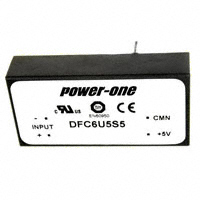
DFC6 Single-Output DC-DC Series Data Sheet
Features
• RoHS lead solder exemption compliant
• Ultra-wide 3.5 to 16 volt input range
• Input filtered
• 6 watts of output power
• Efficiencies to 77%
• 700 V isolation
• Low input-to-output capacitance
• Ultra-wide input range (4:1)
BOTTOM VIEW
2.00
(50.80)
0.300
(7.62)
3.5
3 .5
3.5
3.5
16
16
16
16
5
5.2
12
15
1200
1200
500
4 00
1.00
(25.40)
2
4
0.45
(11.43)
Max
1
0.000
0.200
(5.08)
0.500
(12.70)
0.60
(15.2)
0.3
(7.62)
DFC6U5S5
DFC6U5S5.2
DFC6U5S12
DFC6U5S15
Min
Output
mA
0.80
(20.32)
Model
Output
V DC
0.000
Input Range
VDC (4)
3
0.60
(15.2)
Selection Chart
SIDE VIEW
.040 (1.02) DIA
4 PLACES
0.000
Description
Designed for digital, ECL, and analog application, the
DFC6 Series will provide up to 6 watts in an industry
standard package. Ultra-wide input voltage range
allows operation from battery power as well as system
power. The output is electrically isolated, thereby
allowing the output to be configured as a positive or
negative output voltage. Fully-isolated and filtered
outputs permit usage in sensitive and low noise
circuits.
The 100 kHz operating frequency of the DFC6 Series
allows an increased power density while including
adequate heatsinking and input/output filtering. This
eliminates the need for external components in most
applications.
Mechanical tolerances unless otherwise noted:
X.XX dimensions: ±0.020 inches
X.XXX dimensions: ±0.005 inches
General Specifications (1)
All Models
Isolation
Isolation Voltage
Input to Output
10μA Leakage
Input to Output
Capacitance
Environmental
Case Operating Range, Tc
No Derating
Case Functional Range (2)
Storage Range
Thermal Impedance (3)
Units
MIN
700
VDC
TY P
300
pF
MIN
MAX
MIN
MAX
MIN
MAX
TYP
-40
85
-50
100
-55
105
19
°C
°C
°C
°C/Watt
General
MTBF (Calculated)
Unit Weight
Chassis Mounting Kit
REV. JAN 26, 2006
TY P
TYP
800,000
0.9 / 25.6
CM2B1
HRS
oz / gm
Pin
1
2
3
4
Function
+INPUT
-INPUT
+OUT
-OUT
NOTES
(1) All parameters measured at Tc=25 °C, nominal input voltage and full rated
load unless otherwise noted.
(2) The functional temperature range is intended to give an additional data
point for use in evaluating this power supply. At the low functional
temperature the power supply will function with no side effects. However,
sustained operation at the high functional temperature will reduce
expected operational life. The data sheet specifications are not
guaranteed beyond the case operating range.
(3) The case thermal impedance is specified as the case temperature rise
over ambient per package dissipated.
(4) Reduced output power available with 3.5 V input. Full power is available
above 4.6 V input. See input voltage derating curve for more information.
Page 1 of 3
www.power-one.com
�DFC6 Single-Output DC-DC Series Data Sheet
Input Parameters (1)
Model
DFC6U5S5
Voltage Range (2)
Input Current
Full Load
No Load
Switching Frequency
Maximum Input Overvoltage,
100ms Maximum
Turn-on Time,
1% Output Error
MIN
MAX
TYP
TYP
TYP
DFC6U5S5.2
DFC6U5S12
DFC6U5S15
1680
10
1670
20
3.5
16
1680
10
1750
10
Units
VDC
mA
100
kHz
MAX
20
VD C
TYP
10
ms
Output Parameters (1)
Model
Output Voltage
Output Voltage Accuracy
Rated Load Range (5)
Load Regulation
25% Max Load - Max Load
Line Regulation
Vin = Min-Max VDC
Short Term Stability (4)
MIN
TYP
MAX
MIN
MAX
TYP
MAX
TYP
MAX
TYP
Long Term Stability
TYP
Noise, Peak - Peak (3)
RMS Noise
TYP
TYP
TYP
MAX
Temperature Coefficient
DFC6U5S5
DFC6U5S5.2
DFC6U5S12
DFC6U5S15
Units
5
4.95
5.00
5.05
0
1200
0.3
0.7
5.2
5.15
5.20
5.25
0
1200
0.3
0.7
12
11.900
12.000
12.100
0
500
0.1
0.5
15
14.900
15.000
15.100
0
400
0.1
0.5
VDC
0.1
0.2
< 0.05
75
20
%/kHrs
50
10
40
8
mVPP
m V rm s
ppm/°C
Short Term Current Limit
NOTES
(1) All parameters measured at Tc=25 °C, nominal input voltage and full rated
load unless otherwise noted.
(2) Reduced output power available at 3.5 V input. Full output power is available
above 4.6 V input. See input voltage derating curve for more information.
(3) Noise measurement bandwidth is 0-20 MHz for peak-to-peak measurements,
10 kHz to 1 MHz for RMS measurements. Output noise is measured with a
1μF/35V Tantalum capacitor located 1" away from the converter to simulate
PCB standard decoupling.
(4) Short term stability is specified after a 30-minute warmup at full load, constant
line, and recording the drift over a 24-hour period.
(5) No minimum load required for operation. Dynamic regulation may degrade
when run with less than 5% load.
DFC6 Series Application Notes:
External Capacitance Requirements
No external capacitance is required for operation of the
DFC6 Series. To meet the reflected ripple requirements of
the converter, an input impedance of less than 0.15 Ohms
from DC to 200 kHz is required. If a capacitive input
source is farther than 1” from the converter, an additional
REV. JAN 26, 2006
%
%/24Hrs
50
150
Short Circuit Protection to
Common for all Outputs
mA
%
< 0.1
75
20
VDC
Page 2 of 3
capacitor may be required at the input pins for
proper operation. External output capacitance is
not required for operation, however it is
recommended that 1 μF to 10 μF of tantalum
and 0.001 to 0.1 μF ceramic capacitance be
selected for reduced system noise. Additional
output capacitance may be added for increased
filtering, but should not exceed 400 μF.
Output Power
The available output power of the DFC6 Series
is reduced when operating below 4.6 volts. See
Input Voltage Derating curve. Below 4.6 volts the
output power is linearly derated from 100% at
4.6 volts to 50% at 3.5 volts.
Negative Outputs
A negative output voltage may be obtained by
connecting the +OUT to circuit ground and
connecting -OUT as the negative output.
www.power-one.com
�DFC6 Single-Output DC-DC Series Data Sheet
OUTPUT POWER DERATING
DFC6 SERIES BLOCK DIAGRAM
6
SHIELDED ISOLATION TRANSFORMER
3
5
POWER OUTPUT
+ OUTPUT
+
1
+ INPUT
2
– INPUT
4
CURRENT
MODE
PWM
+
- OUTPUT
+
4
3
2
–
ISO AMP
1
LOW TC
BANDGAP
REFERENCE
NONCONDUCTIVE PLASTIC CASE
0
40
50
60
70
80
AMBIENT TEMPERATURE
90
Typical Performance: (Tc=25°C, Vin=Nom VDC, Rated Load)
EFFICIENCY Vs. LOAD
INPUT CURRENT (AMPS)
70
LINE = 16VDC
3.5
3.0
2.5
2.0
1.5
100% LOAD
1.0
0.5
50% LOAD
60
0
10
20
30
40
50
60
70
80
0.0
90 100
0
2
LOAD (%)
EFFICIENCY Vs. LINE INPUT VOLTAGE
RMS INPUT CURRENT (AMPS)
EFFICIENCY (%)
50% FULL LOAD
75
100% FULL LOAD
70
65
8
10
10
12
14
.1
5 VOLT OUTPUT
16
100
12
LINE INPUT (VOLTS)
14
16
1.0
75% LOAD
0.6
50% LOAD
0.4
0.2
0.0
7
100000
1000000
INPUT VOLTAGE DERATING
0.8
5
10000
120
100% LOAD
3
1000
FREQUENCY (Hz)
RMS INPUT CURRENT Vs. LINE INPUT
80
6
8
6
12/15 VOLT OUTPUT
1
LINE INPUT (VOLTS)
85
4
4
10
.01
10
% AVAILABLE POWER
EFFICIENCY (%)
75
OUTPUT IMPEDENCE (OHMS)
4.0
LINE = 5VDC
65
OUTPUT IMPEDENCE Vs. FREQUENCY
INPUT CURRENT Vs. INPUT VOLTAGE
80
9
11
13
LINE INPUT (VDC)
15
17
100
80
60
40
20
0
3.50
3.75
4.00
4.25
4.50
4.75
5.00
LINE INPUT (VDC)
NUCLEAR AND MEDICAL APPLICATIONS - Power-One products are not designed, intended for use in, or authorized for use as critical components
in life support systems, equipment used in hazardous environments, or nuclear control systems without the express written consent of the respective
divisional president of Power-One, Inc.
TECHNICAL REVISIONS - The appearance of products, including safety agency certifications pictured on labels, may change depending on the
date manufactured. Specifications are subject to change without notice.
REV. JAN 26, 2006
Page 3 of 3
www.power-one.com
�
很抱歉,暂时无法提供与“DFC6U5S5”相匹配的价格&库存,您可以联系我们找货
免费人工找货