HP Series
120 - 192 Watt 10:1 DC-DC Converters
These extremely compact DC-DC converters incorporate all
necessary input and output filters, signaling and protection
features, which are required in the majority of applications.
The converters provide important advantages, such as flexible
output power through total current limitation, extremely high
efficiency, excellent reliability, very low ripple and RFI noise
levels, full input-to-output isolation, negligible inrush current,
soft start, over temperature protection, interruption time, and
input over- and undervoltage lockout.
Features
111
4.4"
3U
20
0.8"
4 TE
164
6.5"
®
• Extremely wide input voltage range from 12.5 to 154 VDC
in the same model
• RoHS-compliant
• 5 year warranty
• Class I equipment
• Compliant with EN 50155, EN 50121-3-2, and
IEC/EN 61000-4-2, -3, -4, -5, -6, -8
• Fire&smoke: Compliant with EN 45545-2
• Input over- and programmable undervoltage lockout
including inhibit function
• Low inrush current
• 10 ms interruption time
• 1 to 4 independent, isolated outputs: no load, overload,
and short-circuit proof
• Rectangular current limiting characteristic
• Redundant operation (n+1), sense lines, active current
sharing option, output voltage adjust
• Hipot test voltage 2.8 kVDC
• Very high reliability and efficiency up to 92.5 %
• All PCB boards protected by lacquer
• Extremely slim case (4 TE, 20 mm), fully enclosed
Safety-approved to IEC/EN 62368-1 3rd edition and
UL/CSA 62368-1 3rd edition.
Table of Contents
Description........................................................................................2
Model Selection.................................................................................2
Functional Description.......................................................................5
Electrical Input Data..........................................................................8
Electrical Output Data..................................................................... 11
Auxiliary Functions..........................................................................18
Electromagnetic Compatibility (EMC)..............................................20
Immunity to Environmental Conditions............................................22
Mechanical Data..............................................................................24
Safety and Installation Instructions..................................................25
Description of Options.....................................................................27
Accessories.....................................................................................28
belfuse.com/power-solutions
BCD.00316_AR
21 June 2023
�HP Series
120 - 192 W 10:1 DC-DC Converters
DESCRIPTION
The converters are particularly suitable for rugged environments, such as railway applications. They have been designed in
accordance with the European railway standards EN 50155 and EN 50121-3-2. All printed circuit boards are coated with a protective
lacquer. The converter covers a total input voltage range from 12.5 to 154 VDC in the same model. The input is protected against
surges and transients occurring on the source lines. The outputs are continuously open- and short-circuit proof.
Full system flexibility and n+1 redundant operating mode are possible due to series or parallel connection capabilities of the outputs
under the specified conditions. When several converters with T option are connected in parallel, a single-wire connection between
these converters ensures good current sharing. LEDs at the front panel and an isolated output OK signal indicate the status of the
converter. Voltage suppressor diodes and an independent overvoltage monitor protect the outputs against an internally generated
overvoltage.
The converters are designed using transformers with planar technology. The input voltage is fed to a booster, which generates
approximately 70 V. If Vi is higher, the booster becomes simply a diode. The resulting intermediate voltage supplies the powertrains.
There are two powertrains fitted to a converter, each consisting either of a regulated single output with synchronous rectifier or of a
regulated main output with a tracking second output. The output power may be flexibly distributed among the main and the tracking
output of each powertrain. Close magnetic coupling in the transformers and output inductors together with circuit symmetry ensure
a small deviation between main and tracking output.
A storage capacitor charged to approx. 70 V enables the powertrains to operate during the specified interruption time.
As part of a distributed power supply system, the low-profile design significantly reduces the required volume without sacrificing
high reliability. The converters are particularly suitable for 19” rack systems occupying 3 U /4 TE only, but they can also be chassismounted by screws or fitted with a heat sink. The connector type is H15. The fully enclosed black-coated aluminum case acts as
heat sink and RFI shield, such protecting the converter together with the coating of all components against environmental impacts.
MODEL SELECTION
Note: Only standard models are listed. Other voltage configurations are possible on request.
Table 1: Model Selection
Output 1, 4
Output 2, 3
Input voltage
Efficiency
η
86.5
89
91
89.5
89
154
16.8 - 137.5
16.8 - 137.5
Po 506
[W]
Vo nom
[V]
Po nom5
[W]
Po 506
[W]
5.1
12
15
24
122
122
122
122
184
192
192
192
-
-
-
5.1
5.1
5.1
12
15
61
61
61
61
61
92
92
92
96
96
5.1
12
15
12
15
61
61
61
61
61
92
96
96
96
96
12.5
16.8 - 137.5
24
60
96
24
60
96
12.5
5.1
5.1
5.1
61
61
61
92
92
92
12, 12
15, 15 4
24, 24 4
60
60
60
96
96
96
12.5
12, 12 4
15, 15 4
15, 15 4
24, 24 4
60
60
60
60
96
96
96
96
12, 12 4
15, 15 4
24, 24 4
24, 24 4
60
60
60
60
96
96
96
96
1
2
3
4
5
6
7
12.5
12.5
Vi cont
[V]
16.8 - 137.5
16.8 - 137.5
Options
η 110
typ
[%]
Po nom5
[W]
Model
2
min
[%]
Vo nom
[V]
4
Vi min3
[V]
1
24
min
[%]
typ
[%]
87
90.5
92.5
91
90
HP1001-9RTG
HP1301-9RTG
HP1501-9RTG
HP1601-9RTG
U, V, B
86.5
89
90
89.5
91
89.5
87
90.5
91.5
91
92.5
91
HP2001-9RG
HP2020-9RG
HP2040-9RG
HP2320-9RG
HP2540-9RG
U, V, T 7, B
154
86.5
88
87
89.5
HP2660-9RG
U, V, B
154
86.5
88.5
88
89
87
90
90
90
HP3020-9RG
HP3040-9RG
HP3060-9RG
U, V, T 7, B
86.5
88
88
88
88
87
90
89.5
89.5
89.5
HP4320-9RG
HP4540-9RG
HP4560-9RG
HP4660-9RG
U, V, B
Vi max3
[V]
154
154
Efficiency at TA = 25 °C, Vi = 24 V, Io nom, Vo nom
Efficiency at TA = 25 °C, Vi = 110 V, Io nom, Vo nom
Short time; see table 2 for details!
Isolated tracking output
Po nom is specified at Tamb = 70 °C
Po 50 is specified at Tamb = 50 °C and Vi = ≥ 22 V. For Vi = ≤ 22, only 90% of Po 50 are continuously possible
T replaces R
Asia-Pacific
+86 755 298 85888
EMEA
+353 61 49 8941
North America
+1 866 513 2839
tech.support@psbel.com
belfuse.com/power-solutions
© 2023 Bel Fuse Inc.
BCD.00316_AR
21 June 2023
Page 2 of 28
�HP Series
120 - 192 W 10:1 DC-DC Converters
Part Number Description
H P 4 6 60 -9 R B1 G
Continuous operating input voltage Vi :
16.8 to 137.5 VDC................................................ H
Series
. ............................................................................. P
Number of outputs:
Single output (160 mm case) 4. ............................. 1
Double output (160 mm case) 4............................. 2
Triple output (160 mm case) 4. .............................. 3
Quadruple output (160 mm case) 4. ...................... 4
Nominal voltage output 1 /output 4, Vo1/4 nom:
5.1 V...................................................................... 0
12 V....................................................................... 3
15 V....................................................................... 5
24 V....................................................................... 6
other voltages 1.................................................. 7, 8
Other specifications and additional features1 .............. 01, ... 99
Nominal voltage output 2 /output 3, Vo2/3 nom:
5.1 V.................................................................... 01
12 V..................................................................... 20
15 V..................................................................... 40
24 V..................................................................... 60
other voltages and features 1..................... 80, ... 99
Operational ambient temperature range TA:
– 40 to 71 °C......................................................... -9
other 1 ................................................................... 0
Output voltage adjust (auxiliary function)............................... R 3
Options:
Current sharing.................................................... T 2
UVL (preadjusted Vi min).................................... Uxx 5
V (rotary switch to adjust Vi min).............................V 6
Heatsink 10, 20, 30 mm..........................B0, B1, B3
RoHS-compliant for all 6 substances.......................................G
Customer-specific models.
Only available for single-output powertrains. Option T excludes option R, except for single-output models; refer to table 12.
T is standard for single-output models
3
The R-input influences the first power train only; refer to table 12.
4
Models with 220 mm case length. Just add 5000 to the standard model number, e.g. HP3020-9RG → HP8020-9RG.
5
For full compatibility with former P Series, the start voltage can be preadjusted depending on the nominal battery voltage. Excludes opt. V.
6
Excludes opt. U.
1
2
Note: The sequence of options must follow the order above.
Example: HP4660-9RB1G: DC-DC converter, input voltage 16.8 to 137.5 V, 4 outputs providing 24 V each, heatsink B1,
ambient temperature of – 40 to 71 °C, RoHS-compliant.
Note: All models exhibit the following auxiliary functions, which are not reflected in the type designation: input and output filters, primary referenced
PUL (programmable undervoltage shutdown with inhibit function), sense lines (single-, double-, triple-output models only), and LED indicators.
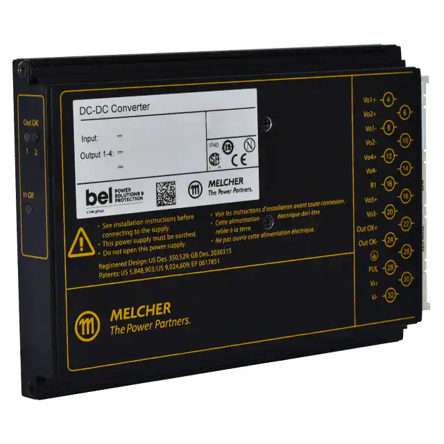
Product Marking
Basic type designation, approval marks, CE mark, warnings, pin allocation, patents, MELCHER logo, specific type designation,
input voltage range, nominal output voltages and output currents, degree of protection, identification of LEDs, batch no., serial no.
and data code including production site, version, and production date.
Asia-Pacific
+86 755 298 85888
EMEA
+353 61 49 8941
North America
+1 866 513 2839
tech.support@psbel.com
belfuse.com/power-solutions
© 2023 Bel Fuse Inc.
BCD.00316_AR
21 June 2023
Page 3 of 28
�HP Series
120 - 192 W 10:1 DC-DC Converters
Output Configuration
The HP Series allows high flexibility in output configuration to cover almost every individual requirement, by simply wiring outputs
in parallel, in series, or in independent configuration, as shown in the following diagrams.
Parallel or serial operation of several converters with equal output voltage is possible, using the current share option T to provide
reasonable current sharing. Choose suitable single-output models, if available.
Note: Unused tracking outputs should be connected in parallel to the respective regulated outputs.
JM144a
Single-output
model
i
28
PUL
RPUL
JM145a
4
Double-output
model
Vo2+
6
Vo+
6
S2+
18
S+
12
S2–
20
OK+
22
Vo2–
10
OK–
24
Vo1+
4
R
16
Vo+
i
Load
RPUL
Vi+
S–
14
30
Vi+
S1+
12
32
Vi–
Vo–
8
32
Vi–
S1–
14
Vo–
10
Vo1–
Fig. 1b
Series output configuration of a double-output model.
The second output is fully regulated.
JM146a
JM147a
4
Triple-output
model
Vo1+
4
S1+
12
S1+
12
S1–
14
S1–
14
Vo1–
8
Vo1–
8
Vo2+
6
Vo2+
6
28
PUL
30
Vi+
S2+
18
32
Vi–
S2–
20
Vo2–
10
Load 1
i
28
Load 2
Vi+
Vo2–
10
32
Vi–
Vo3+
18
Vo3–
20
Load 2
Load 3
JM149b
4
8
Load 1
Vo4+
12
Load 4
Vo4–
14
Vo2+
6
10
RPUL
30
Load 1
Fig. 1d
Independent triple-output configuration. Output 3 is tracking
JM148b
Quadrupleoutput
Vo1+
model
Vo1–
PUL
PUL
RPUL
Fig. 1c
Independent double-output configuration. Both outputs are
fully regulated
28
Load
8
Double-output
model
Vo1+
RPUL
i
PUL
30
Fig. 1a
Standard configuration (single-output model)
i
28
30
Vi+
Vo2–
32
Vi–
Vo3+
18
Vo3–
20
Load 2
Load 3
Fig. 1e
Common ground configuration of output 1 with 4 and
independent configuration of output 2 and 3
Quadruple- Vo3+
output
Vo3–
model
i
28
PUL
RPUL
18
20
Vo2+
6
Vo2–
10
Vo4+
12
Vo4–
14
30
Vi+
Vo1+
4
32
Vi–
R
16
Vo1–
8
Load
R2
R1
Fig. 1f
Series configuration of all outputs (Vo = 96 V for HP4660).
The R-input influences only outputs 1 and 4. For the values
of R1 and R2 see Output Voltage Adjust.
Asia-Pacific
+86 755 298 85888
EMEA
+353 61 49 8941
North America
+1 866 513 2839
tech.support@psbel.com
belfuse.com/power-solutions
© 2023 Bel Fuse Inc.
BCD.00316_AR
21 June 2023
Page 4 of 28
�HP Series
120 - 192 W 10:1 DC-DC Converters
FUNCTIONAL DESCRIPTION
The converters are designed using transformers with planar technology. The input voltage is fed to a booster, which generates
a voltage of approx. 70 V. If Vi is higher, the booster becomes simply a diode. The storage capacitor Chu is charged by a current
source to max. 70 V and enables the powertrains to operate during the specified interruption time. The resulting intermediate
voltage, between 45 V (during interruption time) and 154 V, supplies the powertrains.
There are two powertrains fitted to a converter, each consisting either of a regulated single output with synchronous rectifier or of
a regulated main output with a tracking 2nd output.
As part of a distributed power supply system, the low-profile design significantly reduces the required volume without sacrificing
high reliability. The converters are particularly suitable for 19” rack systems occupying 3 U / 4 TE only, but they can also be chassismounted by screws or fitted with a heat sink. Connector type is H15. The fully enclosed Aluminum case acts as heat sink and RFI
shield, such protecting the converter together with the coating of all components against environmental impacts. The converters
are equipped with two independent forward converters, switching 180° phase-shifted to minimize the input ripple current. These
two forward converters are called “powertrains” (PT), exhibiting either a single output with synchronous rectifier or two isolated
outputs, one fully regulated and the other one tracking (semi-regulated), thus providing up to four output voltages. The output
power may be flexibly distributed among the main and the tracking output of a double-output powertrain. Close magnetic coupling
in the transformers and output inductors together with circuit symmetry ensure small deviation between main and tracking output.
The low input capacitance results in low and short inrush current. After the isolating transformer and rectification, the output filter
reduces ripple and noise to a minimum without affecting the dynamic response. Outputs 3 and 4, if available, are tracking (semiregulated). An individual current limiter built in to of each powertrain limits the total output current of that powertrain in an overload
condition. This allows flexible power distribution of the outputs of each powertrain. All outputs can either be connected in series or
in parallel; see Electrical Output Data.
An auxiliary converter provides the bias voltages for the primary and secondary referenced control logic and auxiliary circuits. The
converter is only enabled, if the input voltage is within the operating voltage range and above the programmable undervoltage
lockout threshold (PUL) – such limiting the input current dependent on the nominal battery voltage.
All output are equipped with a suppressor diode and an independent monitor sensing the output voltage of the main output. In the
case of an overvoltage, it influences the control logic respectively.
The temperature is monitored and induces the converter to disable the outputs. After the temperature has dropped, the converter
automatically resumes.
Asia-Pacific
+86 755 298 85888
EMEA
+353 61 49 8941
North America
+1 866 513 2839
tech.support@psbel.com
belfuse.com/power-solutions
© 2023 Bel Fuse Inc.
BCD.00316_AR
21 June 2023
Page 5 of 28
�HP Series
120 - 192 W 10:1 DC-DC Converters
Block Diagrams
R T
16
JM140d
18
Powertrain 1
(200 kHz)
Auxiliary
converter
(190 kHz)
4
12
14
8
Vi+
30
Booster
(135 kHz)
Input filter
Vi–
PE
32
RPUL1
28
A
D
B
C
6
20
Models with
opt. V
Out OK
logic
1 Models with opt. U
Vo+
n.c.
10
Vo–
CY
NTC
PUL logic
1
S–
Vo–
Output
filter
NTC
Powertrain 2
(200 kHz)
CY
26
PUL
+
Chu
Vo+
S+
22
Out OK+
24
Out OK–
4
Vo1+
S1+
Fig. 2a
Block diagram of single-ouput models
R or T
Auxiliary
converter
(190 kHz)
30
Booster
(135 kHz)
Input filter
Vi–
Powertrain 1
(200 kHz)
+
Chu
12
14
8
S1–
Vo1–
CY
NTC
32
Vo2+
S2+
20 S2–
6
PE
CY
26
RPUL1
PUL
28
A
D
B
C
1
Models with
opt. V
PUL logic
18
Powertrain 2
(200 kHz)
Output
filter
10
Vo2–
22
Out OK+
24
Out OK–
CY
NTC
Out OK
logic
1 Models with opt. U
Output 2
Vi+
Output
filter
Output 1
JM141d
16
Fig. 2b
Block diagram of double-output models
Asia-Pacific
+86 755 298 85888
EMEA
+353 61 49 8941
North America
+1 866 513 2839
tech.support@psbel.com
belfuse.com/power-solutions
© 2023 Bel Fuse Inc.
BCD.00316_AR
21 June 2023
Page 6 of 28
�HP Series
120 - 192 W 10:1 DC-DC Converters
R or T
Auxiliary
converter
(190 kHz)
30
Booster
(135 kHz)
Input filter
PE
S1–
Vo1–
6
Vo2+
CY
NTC
32
CY
26
RPUL1
PUL
+
Chu
8
14
28
A
D
B
C
Output
filter
Vo2–
Vo3+
20 Vo3–
10
18
CY
NTC
PUL logic
1
1
Powertrain 2
(200 kHz)
Models with
opt. V
Out OK
logic
Models with opt. U
Output 2
Vi–
Powertrain 1
(200 kHz)
Output 3
Vi+
Vo1+
S1+
4
12
Output
filter
Output 1
JM142d
16
22
Out OK+
24
Out OK–
Fig. 2c
Block diagram of triple-output models
R
30
Booster
(135 kHz)
Input filter
PE
Chu
Vo1–
Vo4+
14
Vo4–
6
Vo2+
10
20
Vo2–
Vo3+
Vo3–
22
Out OK+
24
Out OK–
CY
NTC
32
CY
26
1
RPUL
PUL
+
8
12
28
A
D
B
C
1
1
Models with
opt. V
PUL logic
Powertrain 2
(200 kHz)
Output
filter
18
CY
NTC
Out OK
logic
Models with opt. U
Output 2
Vi–
Output
filter
Vo1+
Output 3
Vi+
Powertrain 1
(200 kHz)
4
Output 4
Auxiliary
converter
(190 kHz)
Output 1
JM143e
16
Fig. 2d
Block diagram of quadruple-output models
Asia-Pacific
+86 755 298 85888
EMEA
+353 61 49 8941
North America
+1 866 513 2839
tech.support@psbel.com
belfuse.com/power-solutions
© 2023 Bel Fuse Inc.
BCD.00316_AR
21 June 2023
Page 7 of 28
�HP Series
120 - 192 W 10:1 DC-DC Converters
ELECTRICAL INPUT DATA
General conditions:
- TA = 25 °C, unless TC is specified.
- Sense lines connected directly at the connector
- R input and PUL-input not connected
Table 2: Input data
Model
HP
Characteristics
Vi
Conditions
min
Operating input voltage continuous
Io = 0 – Io max
16.8
For ≤ 2 s without lockout
TC min – TC max
12.5
24
typ
Unit
max
137.5
154
Nominal input voltage range
Vi abs
Input voltage limits
3 s, without damage
Ii
Typical input current 1
Vi nom, I o nom
Pi 0
No-load input power 1
Vi min – Vi max, Io = 0
P i inh
Idle input power 1, 2
Vi min – Vi max, VPUL = 0 V
Ci
Input capacitance 3
18
µF
Ri
Input resistance
10
mΩ
Iinr p
Peak inrush current
65
A
tinr d
Duration of inrush current
Vi = 137.5 V, I o nom
Start-up time at power on 4
ton
Start-up time after inhibit
3
4
1
2
0 → Vi min, I o nom
Vi min ≥ 16.8 V, I o nom
4
VPUL = 0 → 5 V
(110)
0
110
V
Vi nom
165
see fig. 3
7
1.5
W
7
250
500
250
500
ms
Typical values; dependent on model
Converter inhibited with the PUL-pin
Not smoothed by the inrush current limiter at start-up (for inrush current calculation)
See fig. 14
Input Protection, PUL Function, Fuse
No fuse is incorporated in the converter. Consequently, an external circuit breaker or fuse at system level should be installed to
protect against severe defects; see table 3.
Table 3: PUL specification (typ.) and recommended external fuse depending on the nom. battery voltage
Battery
R PUL
24 V
∞
14.9 V
12.5 V 4
25 A fast, Littlefuse 314 1
36 V
75 kΩ
21.3 V
17 V
16 A fast, Schurter SP 2
48 V
47 kΩ
25.4 V
20.2 V
72 V
16.9 kΩ
43 V
34 V
8 A fast, Schurter SP 2
96 V
10 kΩ
59.5 V
48 V
8 A fast, Schurter SP 2
110 V
7.5 kΩ
71 V
56 V
6.3 A slow, BEL fuse MRT 3
all
< 100 Ω
1
Vi min (on / off)
Fuse recommended
12.5 A fast, Schurter SP 2
Converter disabled
Size 6.3 × 32 mm 2 s ize 5 × 20 mm 3 ∅ 8.35 × 7.7 mm 4 for ≤ 2 s
Note: An internal R PUL is fitted in models with option U in order to provide compatibility with the converters Series BP – EP.
Reverse polarity protection is provided by antiparallel diodes across the input, causing the external circuit breaker or fuse to trip.
A suppressor diode protects against voltage spikes beyond Vi abs.
The converter is designed for an extremely wide input voltage range, allowing for connection to all common railway batteries.
However, the programmable input undervoltage lockout (PUL, pin 28) should be adjusted carefully in order to limit the input current
at start-up; see fig 3.
Asia-Pacific
+86 755 298 85888
EMEA
+353 61 49 8941
North America
+1 866 513 2839
tech.support@psbel.com
belfuse.com/power-solutions
© 2023 Bel Fuse Inc.
BCD.00316_AR
21 June 2023
Page 8 of 28
�HP Series
120 - 192 W 10:1 DC-DC Converters
Ii [A]
Vi min [V]
JM183
JM184a
8
80
7
6
60
5
4
40
3
20
2
1
0
10
Vi [V]
20
30
40
50
60
70
80
90
100
110
120
0
130
Fig. 3
Typ. input current versus input voltage at nominal load (HP4660)
RPUL
0
10
20
30
40
50
60
70
80
90 kΩ
Fig. 4
RPUL versus switch-on voltage
Table 3 shows the values of the resistor R PUL, connected between PUL and Vi–, versus the resultant minimum input voltage and
the resultant maximum input current. Fig. 4 shows more values of R PUL versus start-up voltage. For stationary batteries, a higher
start-up voltage might be advantageous.
Note: If PUL (pin 28) is connected to Vi– (pin 32), the converter is disabled. See also Inhibit Function.
Inrush Current
The converters exhibit small input capacitance C i. However, a short peak current appears when applying the input voltage.
Note: The storage capacitor Chu is charged by a current source and does not contribute to the inrush current.
The peak inrush current can be found by following calculation; see also fig. 5:
Vi source
I inr p = –––––––––
(R ext + R i )
JM001c
Lext
Rext
Converter
Vi+
+
Vo+
Load
Ri
Ci
Vo–
Vi–
Fig 5
Input circuit to calculate the inrush current
Input Stability with Long Supply Lines
If a converter is connected to the power source by long supply lines exhibiting a considerable inductance Lext, an additional external
capacitor Cext connected across the input pins improves the stability and prevents oscillations.
JM085d
Lext
Rext
Vi+
Ri
Converter
Vo+
Cext
Ci
Vi–
Load
+
ri
Vo–
Fig 6
Input configuration to consider stability
Asia-Pacific
+86 755 298 85888
EMEA
+353 61 49 8941
North America
+1 866 513 2839
tech.support@psbel.com
belfuse.com/power-solutions
© 2023 Bel Fuse Inc.
BCD.00316_AR
21 June 2023
Page 9 of 28
�HP Series
120 - 192 W 10:1 DC-DC Converters
Actually, a HP Series converter with its load acts as negative resistor r i, because the input current I i rises, when the input voltage Vi
decreases. It tends to oscillate with a resonant frequency determined by the line inductance L ex t and the input capacitance Cext + Ci
damped by the resistor R ext. The whole system is not linear at all and eludes a simple calculation. One basic condition is given by
the formula:
L ext • Po max dV i
___
Ci + Cext > _________
(r =
)
R ext • Vi min² i dI i
Rext is the series resistor of the voltage source including supply lines. If said condition is not fulfilled, the converter may not reach
stable operating conditions. Worst case conditions are lowest Vi and highest output power Po.
Low inductance L ext of the supply lines and an additional capacitor Cext are helpful. Recommended values for Cext are given in table 4,
which should allow for stable operation up to an input inductance of 2 mH. Ci is specified in table 2.
Table 4: Recommended values for C ext
VB nom
Capacitance
Voltage
24 V
1500 µF
40 V
36 V
1000 µF
63 V
48 V
470 µF
100 V
72 V
220 µF
125 V
110 V
100 µF
200 V
Efficiency
The efficiency depends on the model (output configuration) and on the input voltage. Some examples:
η [%]
η [%]
HP1001-9RTG
JM207
100
Vi = 110 V
90
Vi = 24 V
80
70
60
JM208
100
Vi = 110 V
90
Vi = 24 V
80
70
0
0.2
0.4
0.6
0.8
Po / Po 50
Fig. 7a
Efficiency versus Vi and Po (HP1001)
JM188
Vi = 110 V
Vi = 24 V
80
0
0.2
η [%]
100
90
60
0.4
0.6
Po / Po 50
0.8
Fig. 7b
Efficiency versus Vi and Po (HP2320)
HP3060-9RG
η [%]
HP4660-9RG
JM179a
100
Vi = 110 V
90
Vi = 24 V
80
70
70
60
HP2320-9RG
0
0.2
0.4
0.6
Fig. 7c
Efficiency versus Vi and Po (HP3060)
0.8
Po / Po 5
60
0
0.2
0.4
0.6
0.8
Po / Po 50
Fig. 7d
Efficiency versus Vi and Po (HP2660 and HP4660)
Asia-Pacific
+86 755 298 85888
EMEA
+353 61 49 8941
North America
+1 866 513 2839
tech.support@psbel.com
belfuse.com/power-solutions
© 2023 Bel Fuse Inc.
BCD.00316_AR
21 June 2023
Page 10 of 28
�HP Series
120 - 192 W 10:1 DC-DC Converters
ELECTRICAL OUTPUT DATA
General conditions:
- TA = 25°C, unless TC is specified.
- Sense lines connected directly at the connector
- R-input and PUL-input not connected
Table 5a: Output data for single-output powertrains
Output
Single-output powertrain
Characteristics
min
typ
max
min
typ
max
min
typ
max
Vi nom, Io nom
5.07
5.1
5.13
11.94
12
12.06
14.93
15
15.08
23.88
24
24.12
Vi min – Vi max
TC min – TC max,
(0.02 – 1) Io nom
5.02
5.18
11.82
12.18
14.78
15.23
23.64
7.14
14.3
15.8
17.1
18.9
28.5
Vo P
Overvoltage protection 2
Vo L
Overvoltage shutdown 6
Io
Nom / Max output current 3
Io L
Output current limit
vo noise
Output
noise 4
Switch. frequency
Voltage deviation
td 5
Dynamic
load
regulation
vo tr
Output voltage trim range
(via R-input)
1.1 Vi min – Vi max
(0.1 – 1) Io nom
α vo
Temperature coefficient of Vo
Io nom,
TC min – TC max
1
2
5
6
3
4
Unit
max
Worst case output voltage
Recovery time
24 V
typ
V ow
vod
15 V
min
Output voltage
Total incl. spikes
12 V
Conditions
Vo
1
5.1 V
6.45
6.8
6.5
Vi min – Vi max
TC min – TC max
12 / 18 3
18.5
22.5
15
18
24.36
30
17
28
5.1 / 8.0 3
4.0 / 6.4 3
2.55 / 4.0
10.6
6.6
8.0
4.5
5.5
Vi nom, Io nom
10
15
20
30
BW = 20 MHz
20
30
40
60
0.6
Vi min – Vi max
(0.5 ↔ 1) Io max
0.9
5
2.75
1.0
5
5.61
±0.02
6.5
31.5
14.3
8.2
13.2
8.1
±0.02
13
±0.02
V
ms
5
16.5
A
mVpp
1.5
5
V
26.4
V
±0.02
%/K
If the output voltages are increased above Vo nom through R-input control or remote sensing, the output power should be reduced
accordingly, so that Po max and TC max are not exceeded.
Breakdown voltage of the incorporated suppressor diode at 10 mA (5.1 V) or 1 mA (≥12 V). Exceeding this value might damage the
suppressor diode.
First value is for Po nom (TA = 71 °C), second value for Po 50 (TA = 50 °C); see also Output Power at Reduced Temperature
Measured according to IEC/EN 61204 with a probe described in annex A
Recovery time until Vo returns to ±1% of Vo; see Dynamic Load Regulation
Output voltage limitation by an additional electronic shutdown
Asia-Pacific
+86 755 298 85888
EMEA
+353 61 49 8941
North America
+1 866 513 2839
tech.support@psbel.com
belfuse.com/power-solutions
© 2023 Bel Fuse Inc.
BCD.00316_AR
21 June 2023
Page 11 of 28
�HP Series
120 - 192 W 10:1 DC-DC Converters
Table 5 b: Output data for double-output powertrains. General conditions as in table 5a.
Output
Double-output powertrain
12 V
Main output
Characteristics
Vo
Conditions
Output voltage
1
min
typ
max
min
typ
max
Vi nom, Io nom
11.94
12
12.06
11.76
12
12.24
Vi min – Vi max
TC min – TC max
(0.02 – 1) Io nom
11.82
V ow
Worst case output voltage
Vo P
Overvoltage protection 2
Vo L
Overvoltage shutdown
Io
Nom / Max output current 3
Io L
Output current limit
vo noise
Output noise 4
vod
td 5
Dynamic load
regulation
vo tr
Output voltage trim range
(via R-input)
1.1 Vi min – Vi max
(0.1 – 1) Io nom
α vo
Temperature coefficient of Vo
Io nom,
TC min – TC max
Vi min – Vi max
TC min – TC max
Total incl. spikes
Voltage deviation
Recovery time
12.18
14.3
6
Switch. frequency
Unit
Tracking output
15
15.8
See Output
Voltage Regulation
14.3
15
14.3
none
2.5 / 4.0
2.5 / 4.0
8.2
V
15.8
A
10.6
Vi nom, Io nom
15
15
BW = 20 MHz
30
30
Vi min – Vi max
(0.5 ↔ 1) Io max
1
0.5
4.5
13.2
mVpp
V
0.8
1
ms
See Output
Voltage Regulation
V
%/K
±0.02
Table 5c: Output data for double-output powertrains. General conditions as in table 5a.
Output
Double-output powertrain
15 V
Main output
Characteristics
Vo
Conditions
Output voltage
1
V ow
Worst case output voltage
Vo P
Overvoltage protection
2
Vo L
Overvoltage shutdown
6
Io
Nom / Max output current 3
Io L
Output current limit
vo noise
Output
noise 4
Switch. frequency
Dynamic
load
regulation
Voltage deviation
vod
td
5
Total incl. spikes
Recovery time
24 V
Tracking output
Main output
Unit
Tracking output
min
typ
max
min
typ
max
min
typ
max
min
typ
max
Vi nom, Io nom
14.93
15
15.08
14.7
15
15.3
23.88
24
24.12
23.76
24
24.24
Vi min – Vi max
TC min – TC max,
(0.02 – 1) Io nom
14.78
See Output
Voltage Regulation
23.64
17.1
Vi min – Vi max
TC min – TC max
15.23
18
18.9
17.1
18
17
none
2.0 / 3.2
2.0 / 3.2
6.6
18.9
8.0
28.5
24.36
30
31.5
See Output
Voltage Regulation
28.5
30
none
1.25 / 2.0
1.25 / 2.0
4.3
20
20
25
25
40
40
50
50
vo tr
Output voltage trim range
(via R-input)
1.1 Vi min – Vi max
(0.1 – 1) Io nom
α vo
Temperature coefficient of Vo
Io nom,
TC min – TC max
1
8.1
1.0
16.5
See Output
Voltage Regulation
mVpp
0.8
1
±0.02
ms
2
26.4
V
1.7
1
13
A
5.7
BW = 20 MHz
0.5
31.5
28
Vi nom, Io nom
Vi min – Vi max
(0.5 ↔ 1) Io max
V
See Output
Voltage Regulation
V
%/K
±0.02
If the output voltages are increased above Vo nom through R-input control or remote sensing, the output power should be reduced
accordingly, so that Po 50 and TC max are not exceeded.
2
Breakdown voltage of the incorporated suppressor diode at 1 mA. Exceeding this voltage might damage the suppressor diode.
3
First value is for Po nom (TA = 71 °C), second value for Po 50 (TA = 50 °C); see also Output Power at Reduced Temperature
4
Measured according to IEC/EN 61204 with a probe described in annex A
5
Recovery time until Vo returns to ±1% of Vo; see Dynamic Load Regulation
6
Output voltage limitation by an additional electronic shutdown
1
Asia-Pacific
+86 755 298 85888
EMEA
+353 61 49 8941
North America
+1 866 513 2839
tech.support@psbel.com
belfuse.com/power-solutions
© 2023 Bel Fuse Inc.
BCD.00316_AR
21 June 2023
Page 12 of 28
�HP Series
120 - 192 W 10:1 DC-DC Converters
Parallel and Series Operation
The first outputs of power trains with equal nominal output voltage can be connected in parallel. Where available, we recommend
ordering of option T.
Any output can be connected in series with any other output. If the main and the tracking output of the same power train are
connected in series, consider that the effect of the R-input is doubled.
Notes:
• If a tracking output is not used, connect it in parallel to the respective regulated main output.
• Connection of several outputs in parallel should include measures to approximate all output currents. Single-output power trains exhibit
current-share pins (T), which must be interconnected. If no current-share pins are available, the load lines should exhibit a similar resistance.
• The PUL- pins ( pin 28) should exhibit an individual PUL resistor for each converter. If the shutdown function is used, each PUL-pin must
be controlled individually.
• If several outputs are connected in series, the resulting voltage may exceed the ES1 level and require additional safety measures in order
to comply with international safety standards.
Parallel operation of two double-output converters with series-connected outputs is shown in fig. 9. The link between the T pins
ensures proper current sharing, even though only the first outputs are influenced by T-function. Sense lines are connected directly
at the connector, and load lines have equal length and section.
26
RP
S2+
18
22
Out OK+
S2–
20
24
Out OK –
Vo2–
10
28
PUL
Vo1+
4
30
Vi+
S1+
12
32
Vi–
S1–
14
R Vo1–
8
Double-output
model
Vo2+
6
S2+
18
16
26
–
+
22
Out OK+
S2–
20
24
Out OK –
Vo2–
10
28
PUL
Vo1+
4
30
Vi+
S1+
12
32
Vi–
S1–
14
R Vo1–
8
16
+
6
Fig. 8
Series connection of double-output converters.
Sense lines connected at the connector.
Rp
6
S2+
18
22
Out OK+
S2–
20
24
Out OK –
Vo2–
10
28
PUL
Vo1+
4
30
Vi+
S1+
12
32
Vi–
S1–
14
Vo1–
8
Double-output
T
model
Vo2+
26
–
16
16
6
S2+
18
22
Out OK+
S2–
20
24
Out OK –
Vo2–
10
28
PUL
Vo1+
4
30
Vi+
S1+
12
32
Vi–
S1– 14
+
Vo1–
Load
JM170a
Double-output
T
model
Vo2+
26
Load
+
JM169a
Double-output
Vo2+
model
8
Fig. 9
Parallel operation of 2 double-output converters
with series-connected outputs.
Asia-Pacific
+86 755 298 85888
EMEA
+353 61 49 8941
North America
+1 866 513 2839
tech.support@psbel.com
belfuse.com/power-solutions
© 2023 Bel Fuse Inc.
BCD.00316_AR
21 June 2023
Page 13 of 28
�HP Series
120 - 192 W 10:1 DC-DC Converters
Redundant Systems
An example of a redundant system using converters with 2 regulated outputs (HP2020) is shown in fig. 10. Load 1 is powered with
5.1 V and load 2 with 12 V.
The converters are separated with ORing diodes. If one converter fails, the remaining one still delivers the power to the loads.
If more power is needed, the system may be extended to more parallel converters (n+1 redundancy).
Current sharing of the 5.1 V outputs is ensured by the interconnected T pins, whereas the sense lines are connected after the
ORing diodes to maintain the correct output voltage.
For the 12 V outputs, no active current-share feature is available. As a result, 2 little diodes Ds (loaded by small resistors R s)
simulate the voltage drop of the ORing diodes. Reasonable current sharing is provided by load lines of equal length and section.
JM171a
Rp
DS
S2+
Out OK+
S2–
Out OK–
Vo2–
PUL
Vo1+
Vi+
S1+
Vi–
S1–
RS
Load 2
+
Double-output
T
model
26
Vo2+
Vo1–
S2+
–
+
Out OK+
S2–
Out OK–
Vo2–
PUL
Vo1+
Vi+
S1+
Vi–
S1–
DS
RS
Load 1
Double-output T
model
Vo2+
26
Vo1–
Wires of equal length and section
Fig. 10
Redundant configuration (example)
Hot Swap
In applications using the hot swap capabilities, dynamic output voltage changes during plug-in and plug-out operations may occur.
Asia-Pacific
+86 755 298 85888
EMEA
+353 61 49 8941
North America
+1 866 513 2839
tech.support@psbel.com
belfuse.com/power-solutions
© 2023 Bel Fuse Inc.
BCD.00316_AR
21 June 2023
Page 14 of 28
�HP Series
120 - 192 W 10:1 DC-DC Converters
Output Voltage Regulation
Line and load regulation of the regulated outputs is so good that input voltage and output current have virtually no influence to the
output voltage.
If a tracking output is not loaded, its output voltage may rise considerably. Thus, unused tracking outputs should be connected in
parallel to the respective main output.
The dynamic load regulation is shown in fig. 11.
Vo
Vod
Vo ±1%
Vo ±1%
Vod
td
td
t
Io /Io nom
1
0.5
≥ 10 µs
≥ 10 µs
0
05102c
t
Fig. 11
Typical dynamic load regulation of the output voltage
Tracking Outputs
The main outputs 1 and 2 are regulated to Vo nom independent of the output current. If the loads on outputs 3 and 4 are too low
(300 2
>300 2
>100
>100
>300 2
>100
>100
MΩ
Creepage distances
5.0
3.5
1.5
3.5
1.5
1.0
mm
1.0 / 0.5
3
3
Pretest of subassemblies in accordance with IEC/EN 62368-1 3rd edition
Tested at 500 VDC
3
Second value between outputs of the same powertrain
1
2
Asia-Pacific
+86 755 298 85888
EMEA
+353 61 49 8941
North America
+1 866 513 2839
tech.support@psbel.com
belfuse.com/power-solutions
© 2023 Bel Fuse Inc.
BCD.00316_AR
21 June 2023
Page 26 of 28
�HP Series
120 - 192 W 10:1 DC-DC Converters
DESCRIPTION OF OPTIONS
Option T: Active Current Sharing
For single-output powertrains only. The current-share function should be used, when several powertrains are operated in parallel.
Examples could be high reliability n+1 redundant systems or systems providing higher output power.
Using this feature reduces the stress of individual converters and improves the reliability of the system. Interconnection of the currentsharing pins T causes the converters to share their output currents evenly.
In redundant systems, the outputs of the converters have to be decoupled by ORing diodes. Consequently, a failure of one converter
will not lead to a system failure.
To ensure correct operation of the current-share function, the installer must ensure that the S– pins of all parallel converters are at the
same electrical potential and that there are no voltage drops across the connecting lines between these pins.
Double-output converters with outputs connected in series can also be paralleled with current sharing, if pins Vo1– of all converters
are connected together; see fig. 9.
If the output voltages of parallel connected single-output converters are programmed to a voltage other than Vo nom by means of the
R-pin, the outputs should be adjusted individually within a tolerance of ±1%.
Note: The T-function influences Vo1 only.
Option U: Preadjusted Undervoltage Lockout UVL
For compatibility with former P Series converters, the start-up and the shutdown voltage are preadjusted depending on the nominal
battery voltage. In addition, pin 28 (i) is used as inhibit; refer to the clause Primary Inhibit below.
Table 14 defines the start-up and shutdown voltages. For the recommended fuses, refer to table 3.
Option V: Rotary Switch to Adjust UVL
Converters with option V allow for adjustment of the shutdown voltage by means of a 4 position rotary switch, accessible through
a hole in the case. In addition, pin 28 (i) is used as inhibit; refer to the clause Primary Inhibit below.
Table 14 defines the start-up and shutdown voltages. For the recommended fuses, refer to table 3. The rotary switch is set in the
factory to position D.
Primary Inhibit for Option U and V
This inhibit (pin 28) input enables (logic low) or disables (logic high or open-circuit) the output. In systems consisting of several
converters, this feature may be used to control the activation sequence by logic signals or to enable the power source to start up,
before full load is applied.
The output response is shown in fig. 14.
Note: If this function is not used, pin 28 must be connected with pin 32, otherwise the internal logic will disable the output.
Table 14: UVL specification (typ.) for option U and V
Table 15: Inhibit characteristics (models with option U or V)
Battery
Option U
Position (Opt. V)
24 V
U14
A
14.9 V
12.5 V
36 V
U21
B
21.3 V
17 V
3
U42
C
43 V
34 V
110 V
U70
71 V
56 V
72 V
1
for ≤ 2 s
D
Vi min (on /off)
2
factory setting
2
Characteristics
1
also for 96 V battery
3
Vo = on
Vinh
Inhibit
Voltage
Iinh
Inhibit Current
Vo = off
Conditions
min
Vi min – Vi max
TC min – TC max
-1.0
0.8
+2.4
50
Vinh = 0 V
Vinh = 5 V
Vinh = 50 V
typ
max
- 0.01
- 0.06
- 0.2
Unit
°C
Option B0, B1, B3: Heat Sink
The converter is fitted with an additional heat sink.
Table 16: Thermal resistance of the case (approx. values)
Case
Thermal resistance
Thickness of case
Standard, 160 mm long
1.6 K/W
< 20 mm
Case, 220 mm long
1.4 K/W
< 20 mm
Option B0
1.5 K/W
< 30 mm
Option B1
1.4 K/W
< 40 mm
Option B3
1.2 K/W
< 50 mm
1
Add 5000 to the part number.
Asia-Pacific
+86 755 298 85888
EMEA
+353 61 49 8941
North America
+1 866 513 2839
tech.support@psbel.com
belfuse.com/power-solutions
© 2023 Bel Fuse Inc.
BCD.00316_AR
21 June 2023
Page 27 of 28
�HP Series
120 - 192 W 10:1 DC-DC Converters
ACCESSORIES
A variety of electrical and mechanical accessories is available:
• Mating connectors including faston, screw, solder, or press-fit terminals; see Mating Connectors data sheet BCD.20022.
• Front panels, system Schroff, for 19” racks in 3 U configuration 4 TE (G04-Q01), 5 TE (G05-Q01), or 6 TE (G06-Q01). Similar
panels system Intermas available.
• Front panels, system Schroff, for 19” racks in 6 U configuration 5 TE (G05-6HE-Q01)
• Mechanical mounting supports for chassis, DIN-rail, and PCB mounting plate Q (HZZ01215-G) with retention clips Q (HZZ01229-G)
• Connector retention brackets CRB-Q (HZZ01217-G)
• Different cable connector housings (cable hoods)
For additional accessory product information, see the accessory data sheets listed with each product series or individual
model at our website.
H15 female connector, code key system, faston,
screw or other terminals
Connector retention bracket HZZ01217-G
Mounting plate Q for wall mounting (HZZ01215-G)
with connector retention clips Q (HZZ01229-G)
Universal mounting bracket for DIN-rail and chassis mounting
(HZZ00610-G).
Front panel kit G05-6HE-Q01 (HZZ00838) accommodating
two HP units for a 19” DIN-rack with 6 U, 5 TE.
NUCLEAR AND MEDICAL APPLICATIONS - These products are not designed or intended for use as critical components in life support systems,
equipment used in hazardous environments, or nuclear control systems.
TECHNICAL REVISIONS - The appearance of products, including safety agency certifications pictured on labels, may change depending on the
date manufactured. Specifications are subject to change without notice.
Asia-Pacific
+86 755 298 85888
EMEA
+353 61 49 8941
North America
+1 866 513 2839
tech.support@psbel.com
belfuse.com/power-solutions
© 2023 Bel Fuse Inc.
BCD.00316_AR
21 June 2023
Page 28 of 28
�