Accessories
Mounting Supports
®
Description
Special mounting supports have been designed for the
integration of power supplies into switch boards, control
panels, printed circuit boards, etc., using adapters for
chassis-, DIN-rail, or PCB mounting.
The 19-inch cassette type DC-DC and AC-DC converters can
also be chassis mounted with frontal access by means of a
special Chassis Mounting Plate, attached to the converters.
The Universal Mounting Bracket also fits to most of these
cassette type converters, allowing for either vertical chassis
or DIN-rail mounting.
Table of Contents
A Bracket Kit, consisting of a PCB with screw terminal
connectors and a bracket suitable for either chassis- or DINrail mounting, is available either for PCB mountable PSR and
PSA Switching Regulators with option "Y" pins or for small
DC-DC converters 1 – 15 Watt.
For isolation of the PCB-mountable converters from a double
sided PCB, the use of Isolation Pads is recommended, as
described below.
Note: All dimensions are in mm, unless otherwise specified.
Page
Page
Description ............................................................................ 1
Chassis Mounting Plates ...................................................... 2
DIN- and Chassis Mounting Brackets .................................. 4
Universal Mounting Bracket ................................................. 9
Isolation Tags for PCB Mounting ........................................ 11
PCB Tags for PCB Mounting .............................................. 11
BCD.20007 Rev AA, 5-Oct-09
Page 1 of 11
www.power-one.com
�Accessories
Mounting Supports
®
Chassis Mounting Plates
For chassis mounting of 19" cassette-style converters, where
only frontal access to the mounting screws is given, special
chassis mounting plate adapters are available according to
the following table and figures 1 to 3.
Table 1: Mounting Plate survey
Case
size
Converter
series
Type
Item no.
Delivery content
K02
K 1, PSK 1
Mounting plate K02
Mounting plate,
4 countersunk
screws
S02
S
1,
PSS
Q01
Q
Q03
LPC
Q04
P
Q01
Q
Q03
LPC
Q04
P
M02
M
H02
H
1
1
Mounting plate Q
Mounting plate M
Mounting plate,
4 countersunk
screws,
4 washers
Option B1 necessary
European
Projection
11.2
12021
7.5
6.5
13
140
125
M4 × 10
17.3
133.4
168
30
Option B1 necessary
for K and S Series
5
Fig. 1
Mounting plate K02
Aluminium, black finish
BCD.20007 Rev AA, 5-Oct-09
Page 2 of 11
www.power-one.com
�Accessories
Mounting Supports
®
168
4.5
4.5
12022
European
Projection
M3 × 6
6
18
140
104±0.1
128
∅ 3.6/7.5 × 90
115
127±01
115
3
14
26
20
16.8
Fig. 2b
Retention Clip
[HZZ01209]
133
16.3
115
25.5
6.5
4.5
11.2
12020
6
Fig. 2a
Mounting plate Q with integrated connector retention facility
using the Retention Clip [HZZ01209]
Aluminium, black finish
103.5
M3× 6
Washer
18.5
128
140
∅ 4.5/9 × 90
European
Projection
127
166
19.5
3
Fig. 3
Mounting plate M
Aluminium, black finish
BCD.20007 Rev AA, 5-Oct-09
Page 3 of 11
www.power-one.com
�Accessories
Mounting Supports
®
DIN- and Chassis Mounting Brackets
PCB mounting as well as cassette style converters can be
chassis- and/or DIN-Rail mounted by means of Mounting
Bracket adapters. For selection and item numbers refer to
table below.
Note: Customized adapters for other case sizes are available
upon request.
Each item number gives a direct indication of the kind of
mounting, the type of converter, i.e. the case size, or the
output power as well as the possible pinnings and options
according to the relevant converter data. The adaptors are
divided into two mechanical types: CMB and DMB.
Table 2: Mounting Bracket survey
A1
[mm]
A2
[mm]
Converter
case size
95.0
90.0
A01
Converter
series
Chassis-mounting
Part no.
DIN-mounting
Part no.
Delivery
content
PSR, PSA
(Vi max = 40, 60, 80 V)
CMBA01-iRY/80
DMBA01-iRY/80
PSA
(Vi max = 144 V)
CMBA01-iRY/144
DMBA01-iRY/144
PCB, screw teminal blocks,
4 diodes, capacitor C1 and
C- or D-bracket with screws
72.5
67.5
2"×2"
IMR6, IMR15
IMP6, IMP12
CMB2×2-BCFG
DMB2×2-BCFG
50.0
45.0
DIL 24
IMP1, IMP3, IXP3
IMX4 Option K
CMB3W-123
DMB3W-123
72.5
67.5
1"×2"
IMX7, IMS7
IML10
CMB IMS/X7
DMBIMS/X7
PCB, screw teminal blocks,
and C- or D-bracket
See Basic Kit C/DMB IMX/S7
12023
A1
4
4
60
83
85
11.5
12024
13.3
38
3.2
A2
12
Fig. 4
CMB chassis mounting bracket dimensions
Bracket: Aluminium, black finish
BCD.20007 Rev AA, 5-Oct-09
Fig. 5
DMB DIN-rail mounting bracket dimensions
Bracket: Polycarbonate, black
Page 4 of 11
www.power-one.com
�Accessories
Mounting Supports
®
CMB: Chassis Mounting Bracket
The kit consists of a PCB for the converter, a set of screw
terminals allowing for easy electrical connection and two
aluminium profiles, attached to the PCB by means of four
screws, which serve as the chassis mounting bracket. Four
different versions according to table 2 are available.
Details on the layout of the PCBs and diagrams are given in
the description below.
DMB: DIN-Rail Mounting Bracket
The DMB kit differs from the CMB version by a bracket suited
for DIN-rail mounting (according to EN 50022). The black
plastic body of the bracket holds the PCB by means of a
snap-in device. Four different versions according to table 2
are available.
Details on the layout of the PCB's and diagrams are given in
the description below.
12026
C/DMBA01-.. Electrical Description
MB A01-iRY
This bracket is designed for non-isolated Switching
Regulators of the PSR and PSA series in the A01 case size,
equipped with option Y. Technical details and further
information, e.g., max. input voltage etc., are described in the
PSR and PSA data sheets. The use of the optional inhibitand R-function (external output voltage adjustment with R1)
is possible, and the device can be driven either from a DCsource or from a transformer secondary voltage.
– AC-input: The recommended transformer secondary voltage is 48 VAC for PSR/PSA (with Vi max = 80 V) and
72 VAC for PSA (withVi max = 144 V)
Input
Exception: Input voltage for PSR54 (PSA55) is 20 VAC.
1
X1
Vi Gi
Note: PSR54 (PSA55) and PSR362 require an additional
capacitor (C2) of at least 470 μF.
i
1
+
C2
+
C1
D3 D4 D1 D2
X2
G R Go Vo
Output
– DC-input: Consider the forward voltage drop across the
rectifier diodes (also providing reverse polarity protection).
Capacitor C1 compensates the negative input impedance
of the converter in case of long connection wires.
R1
Fig. 6b
C/DMBA01- .. print layout
X1 - 1
D1
12025a
D3
Gi–
D2
D4 C2
+
C1
Vo+
Go–
X1 - 4
PSR/PSA
A01-iRY
+
Vi+
X2 - 3
X2 - 2
R1
R
i
X2 - 1
X1 - 3
C/DMB2×
× 2-BCFG Electrical Description
This bracket allows the mounting of isolated DC-DC
converters IMR6, IMR15, IMP6 and IMP12 in 2"×2" cases with
either one or two output voltages of 5, 12 or 15 V. The
technical details are given in the data sheets of IMR6, IMR15,
IMP6, IMP12.
Depending on the application input transient protection may
be incorporated (e.g. an appropriate Transzorb diode D1).
X1 - 2
Fig. 6a
C/DMBA01- .. circuit diagram
BCD.20007 Rev AA, 5-Oct-09
Page 5 of 11
www.power-one.com
�Accessories
Mounting Supports
®
12027a
X1 - 4
D1
X2 - 1
Vo
(Vo+)
Vi+
IMR 6
IMR 15
Vi– IMP 6 (COM)
IMP 12
X1 - 1
X1 - 2
X2 - 2
voltages. The pin configuration of the converter groups
single, double, and dual, and all technical converter details
are described in the data sheets.
Depending on the application input transient protection may
be incorporated (e.g. an appropriate Transzorb diode D1) .
X2 - 3
12030
X1 - 3
SD
MB 3W-123
X2 - 4
Go
(Vo–)
Input
Output
1
3
4
C2 D1
C1 C3
X2
2
X1
Fig. 7a
C/DMB2×2-BCFG circuit diagram
1
4
12029a
3
2
1
MB 2×2 BCFG
Input
Vi–
Output
X1
2
SD
Fig. 8b
C/DMB3W-123 print layout
4
X2
Vi+
3
2
Basic Kit CMBIMX/S7
1
For use with 1"×2" DC-DC converter types:
IML10, IMS7 and IMX7
D1
Fig. 7b
C/DMB2×2-BCFG print layout
C/DMB3W-123 Electrical Description
This bracket is designed for galvanically isolated DC-DC
converters of the IMP1, IMP3 and IXP3, IMX4 and IMS6 (both
with option K) series in DIL 24 cases with one or two output
The basic kit contains the following:
– Two mounting rails, 83 mm
– Four screws M 2.5×6
– Four nuts M 2.5
– PCB ZGN 09601 A
– Three 2-pole terminal blocks
(2× for X1 terminal, 1× for X3 terminal)
– One 3-pole terminal block for X2 terminal
– Three wire jumpers 5.08 mm (positions B1, B4, B5)
– One wire jumper 10.16 mm (position D1)
– Six wire jumpers 6.8 mm (positions L2, L4, L6)
– Circuit diagram no. YSK25300 S3 01
Basic Kit DMBIMX/S7
For use with 1"×2" DC-DC converter types:
IML10, IMS7 and IMX7
12028a
X1 - 2
X1 - 4
20
1
2
SD
Vi+
Vi+
D1
X1 - 1
23
24
Vi–
Vi–
Vo+
Vo–
Vo2
13
Vo+ 15
IMP 1 Go2 16
IMP 3
11
IXP 3 COM 10
COM
Go+ 9
Vo1/Vo– 12
X2 - 4
X2 - 3
X2 - 2
X2 - 1
The basic kit contains the following:
– DIN-mounting support for 35 mm DIN-rail systems
– PCB ZGN 09601 A
– Three 2-pole terminal blocks
(2× for X1 terminal, 1× for X3 terminal)
– One 3-pole terminal block for X2 terminal
– Three wire jumpers 5.08 mm (positions B1, B4, B5)
– One wire jumper 10.16 mm (position D1)
– Six wire jumpers 6.8 mm (positions L2, L4, L6)
– Circuit diagram no. YSK 25300 S3 01
C1
C2
C3
Fig. 8a
C/DMB3W-123 circuit diagram for all pin configurations
BCD.20007 Rev AA, 5-Oct-09
Page 6 of 11
www.power-one.com
�Accessories
Mounting Supports
®
Application-Specific Circuitry
Mounting Instructions for Basic Kit
The assembly C/DMB IMX/S7 offers a variety of additional
external circuitries which may be implemented onto the PCB
ZGN09601 A. See circuit diagram YSK 25300 S3 01. Please
also consult the IMS/X7 data sheet.
Single output units IML10, IMS7, and IMX7:
– Solder the wire jumpers into positions as below:
1. D1 (10.16 mm)
2. B1 (5.08 mm), inhibit.
Note: This jumper should be fitted, if the inhibit is not actively
used. An open inhibit disables the converter.
3. L2-A and L2-B, L6-A and L6-B (6.8 mm)
4. L4-A and L4-B (6.8 mm), only necessary, if the
R-input is used.
Depending upon the application the following pheripheral
additions can be made:
– Reverse polarity protection by a series diode D1.
– Improved input transient protection according to IEC/EN
61000-4-5, level 2, by chokes L1 or L2-A, L2-B (EMC
version) and capacitor C1.
– Solder terminal blocks
5. X1: Position Vi+/ Vi–, 2-pole terminal block
6. X1: Position i/n.c., 2-pole terminal block
(only necessary in the case of remote inhibit)
7. X3: Position Vo+/ Vo–, 2-pole terminal block
8. X2: Position n.c., R, Vo–, 3-pole terminal block only
necessary in the case of Vo adjustment by e.g. an
external voltage source)
– Remote inhibit.
Note: If the inhibit is not actively used the inhibit has to be
connected to Vi– by jumper B1.
– External output voltage trimming/adjustment
Single output units:
a) Vo – adjustment in the range of 70/75 – 100% of Vo nom by
resistors RX3 or RX4 or combinations of RX3/RX4.
– Solder the selected DC-DC converter
– Mount PCB onto rails by using the 4 screws and nuts or
snap PCB onto the DIN mounting support.
– Perform function test
b) Vo – adjustment in the range of 100 – 105% of Vo nom by
resistors RX1 or RX2 or combinations of RX1/RX2.
Double output units:
Double output units IML10, IMS7, and IMX7:
a) Vo – trimming by resistor R2 in the range of 100 - 105%
of Vo nom
– Solder the wire jumpers into positions as below:
1. D1 (10.16 mm)
2. B1 (5.08 mm), inhibit
b) Vo – trimming in the range of 70/75 - 100% of Vo nom by a
current diode together with a Zener diode D2 applicable
for 24/48 IMS 7 and 20/40 IMX 7 types.
Note: This jumper should be fitted, if the inhibit is not actively
used. An open inhibit disables the converter.
3. L2-A and L2-B, L6-A and L6-B, L4-A and L4-B (all 6.8
mm)
– For applications with both outputs in parallel:
4. Place/solder jumpers B4 and B5, (5.08 mm)
– Improved electromagnetic emission EN 55022, class B,
lead length to load 1 m (class A for 110IMX7 types).
This requires all capacitors and output chokes as per circuit
diagram YSK 25300 S3 /01 whereby the coupling
capacitor C10 connected to Vi– via jumper B2 is foreseen
for 24/48IMS/L types and 20/40/70IMX7 types.
– Solder terminal blocks
5. X1: Position Vi+/ Vi–, 2-pole terminal block
6. X1: Position i/R (Trim), 2-pole terminal block
(only necessary in the case of remote inhibit or
output voltage trimming by an external voltage
source)
7. X3: Position Vo1+/ Vo1–, 2-pole terminal block
8. X2: Position n.c/Vo2+/Vo2–, 3-pole terminal block
For 110IMX7 types the coupling capacitor C11 or C12
should be used connected to Vo+ via jumper B3.
Notes:
– For single-output models or double-output models with both
outputs in parallel, one filter set (L5 or L6-A/L6-B) together with
C7 and C9 is sufficient.
– Solder the selected DC-DC converter
– Mount PCB onto rails by using the 4 screws and nuts or
snap PCB onto the DIN mounting support.
– Perform function test
– Reduced output ripple (by approx. factor 5) by using
chokes L3/L5 together with electrolytic capacitors C8/C9.
– Wire jumpers B2 and B3 should not be mounted together onto
the PCB as this would cause a short circuit.
– The coupling capacitors C10 or C11/12 should be Y2 ceramic
types to maintain the outputs SELV.
– Application specific assemblies are available on request.
BCD.20007 Rev AA, 5-Oct-09
Page 7 of 11
www.power-one.com
�Accessories
Mounting Supports
®
IMX7, IMS7, IML10
X1
D1
BYV27-200
L1
+
L2 - A
n.c.
1
+
Vi
L3
Vo2+ 13
[R]
+
B1
R1
X1
i
Vo2+ 12
[Vo-]
3
C3
470 n
63 V
R2
R
C4
1μ
63 V
i
D2
ZPD
16 V
4
Vo1+ 11
[Vo+]
R
[n.c.]
B2 B3
C5
470 n
63 V
RX4
B5
RX3
Vi–
RX2
2
L2 - B
X1
Vi +
C2
150 n
250 V
D3
E - 2025N
–
X2
12036a
RX1
X1
C11
100 μ
100 V
14
C6
1μ
63 V
L4 - A
L4 - B
Vo1- 10
[Vo–]
X2
-
L5
L6 - A
X3
+
C9
+
180 μ Vo1
50 V
L6 - B
X3
C7
470 n
63 V
B4
X2
+
C8
+
180 μ Vo2
50 V
-
1 for
70IMX7 use 160 V,
for 110IMX7 use 220 V
C10
Ker Y2, 4.7 n, 250 V
C11, Y2, 47 n, 250 V
[ ] = single-output models
C12, Y2, 60 n, 250 V
Fig. 9a
C/DMB circuit diagram with IMX7, IMS7, and IML10
12037
Input
B1
R2
D2
C3
IMS/X 7
C12
C11
B3
D3
R1
B2
C10
Output
B4
C9
x
X3
R (n.c.)
C7
i
Vi–
X1
C6
Vo1– (Vo–)
L5
L6
Vo1+ (Vo+)
Vo2– (Vo–)
C4
Vo2+ (R)
Vi+
C5
L2 L1
C2
Fig. 9b
C/DMB arrangement of the terminals on the PCB for
IMX7, IMS7, and IML10
BCD.20007 Rev AA, 5-Oct-09
x
C2
RX4
RX3
RX2
RX1
B5
L3
L4
n.c.
X2
C8 x
Note: Where the pin/terminal designations for single-output
models deviate from double-output models, they are shown in
brakets.
Page 8 of 11
www.power-one.com
�Accessories
Mounting Supports
®
Universal Mounting Bracket
(DIN- and Chassis Mounting)
UMB-LHMQ
A special Universal Mounting Bracket has been designed for
vertical or upright chassis- and DIN-rail mounting of the 19"
cassette style converters shown in table 3.
49
12031
4
7.5
14
M4
Fig. 10
DIN-rail clamp
Steel, galvanized
Table 3: Mounting bracket survey
Converter
series
L04
PSL
H02, M02
H, M
Q01, Q03, Q04 Q, LPC, P
Bracket
Item no.
Delivery
content
UMB-LHMQ
Alu-profile, two screws and
a DIN-rail clamp with screw
12032
168
84
20.5
127
158
20.5
5
20
5
29
Converter
case size
4.5
5.5
10
5
4
3
14
M4 (3×)
Fig. 11
VMB universal mounting bracket
Aluminium, untreated
BCD.20007 Rev AA, 5-Oct-09
Page 9 of 11
www.power-one.com
�Accessories
Mounting Supports
®
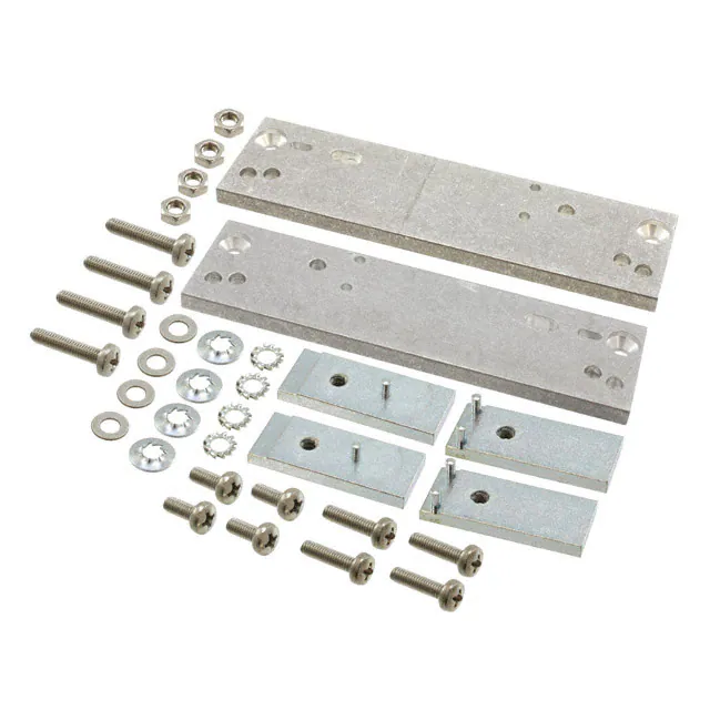
DMB-K/S, DMB-MHQ
By means of these DMB mounting kits, the S, K, PSS, PSK
(DMB-K/S) and the M, H, Q, LPC, P (DMB-MHQ) converters
can be adapted to the DIN-rail. The kit consists of two
aluminium brakets to be mounted on each side of the
converter, including a clamp. The DMB-K/S kit contains two
different sets of screws for the adaption of the brakets either
to S/PSS or K/PSK converter types. The design of the kit is
made such that the fixture is very tight, and as a result the
assembly can also be used for mobile applications.
Table 4: Mounting bracket survey
Case
size
Converter Type
series
item no.
S01
S02
K01
K02
PSS
S
PSK
K
DMB-K/S
M02
H02
Q01
Q03
Q04
M
H
Q1
LPC1
P1
DMB-MHQ
1
Not together with screw-style
connectors STV-H15-FSR(-G)
[HZZ00107]
Fig. 12
Schematic view: Assembly of DMB-K/S
CMB-S
This mounting kit allows for chassis mounting of the S and
PSS Series converters, if access is only possible from the
front of the chassis.
Note: If space conditions are very tight, option B1 or B can be
used instead of the heat sink. Refer to the data sheets of the
respective converters.
This kit uses parts of the DMB-K/S kit since it consists of the
same two brakets but without the clamps and fitted the other
way round on the heat sink.
Table 5: Mounting bracket survey
Case
size
Converter Type
series
Part no.
S01
S02
PSS
S
CMB-S
BCD.20007 Rev AA, 5-Oct-09
Page 10 of 11
www.power-one.com
�Accessories
Mounting Supports
®
Isolation Pads for PCB Mounting
In applications, where PCB mounting converters are placed
on top of double sided boards, the use of Isolation Pads is
recommended. These fibre pads avoid short circuits and
provide excellent protection against possible damage to
tracks. For selection and item numbers refer to table below.
Table 6 : Isolation Pad survey
Case
size
Converter Isolation pad Dimensions
series
[mm]
Item
no.
A01
PSR, PSA Isolation A
70 × 50 × 0.3
B02
PSB
Isolation B
107 × 71 × 0.3 ISLOATIONB,B02
C03
PSC
Isolation C
152 × 86 × 0.3 ISOLATIONC,C03
2"×2"
IMR 6/15
Isolation 2"×2" 53 × 53 × 0.3
ISOLATIONA,A01
ISOLATION2"×2"
PCB-Tags for PCB Mounting
Switching Regulators in B02 or C03 cases may also be
mounted directly onto PCBs. The connection between the
converters' fast-on pins and the PCB can be easily made by
means of PCB-Tags.
Delivery content:
Part number:
10 pieces
LOETGABEL(10x)
1
17
5
7
12035
5
1
5.08
Fig. 13
PCB-Tag
NUCLEAR AND MEDICAL APPLICATIONS - Power-One products are not designed, intended for use in, or authorized for use as critical components
in life support systems, equipment used in hazardous environments, or nuclear control systems without the express written consent of the
respective divisional president of Power-One, Inc.
TECHNICAL REVISIONS - The appearance of products, including safety agency certifications pictured on labels, may change depending on the
date manufactured. Specifications are subject to change without notice.
BCD.20007 Rev AA, 5-Oct-09
Page 11 of 11
www.power-one.com
�