Features
■ Single Turn / Cermet / Industrial / Sealed
■ RoHS compliant* version available
■ Available on tape and reel
■ For trimmer applications/processing
■ Available with a knob for finger adjust
guidelines, click here
■ Available with extended shaft
■ Available with cross-slot rotor
■ Top and side adjust types (F, P, H, W, X
most popular)
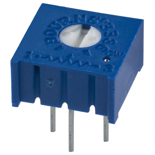
3386 – 3/8 ˝ Square Trimpot® Trimming Potentiometer
Additional Information
Product Dimensions
Click these links for more information:
PRODUCT TECHNICAL INVENTORY SAMPLES
SELECTOR LIBRARY
CONTACT
Electrical Characteristics
Standard Resistance Range
....................... 10 ohms to 2 megohms
(see standard resistance table)
Resistance Tolerance .............±10 % std.
(tighter tolerance available)
Absolute Minimum Resistance
........................................ 2 ohms max.
Contact Resistance Variation
.............................2 % or 3 ohms max.
(whichever is greater)
Adjustability
Voltage Divider ........................±0.05 %
Rheostat ..................................±0.15 %
Resolution..................................... Infinite
Insulation Resistance ................ 500 vdc.
1,000 megohms min.
Dielectric Strength
Sea Level ................................ 900 vac
70,000 Feet ............................. 350 vac
Adjustment Angle................... 280 ° nom.
Environmental Characteristics
Power Rating (300 volts max.)
85 °C ....................................... 0.5 watt
125 °C ........................................ 0 watt
Temperature Range .... -55 °C to +125 °C
Temperature Coefficient .....±100 ppm/°C
Seal Test .......................85 °C Fluorinert†
Humidity......... MIL-STD-202 Method 103
96 hours
(2 % ΔTR, 10 Megohms min.)
Vibration ....... 30 G (1 % ΔTR; 1 % ΔVR)
Shock.......... 100 G (1 % ΔTR; 1 % ΔVR)
Load Life .. 1,000 hours 0.5 watt @ 70 °C
(3 % ΔTR; 3 % or 3 ohms,
whichever is greater, CRV)
Rotational Life.........................200 cycles
(4 % ΔTR; 3 % or 3 ohms,
whichever is greater, CRV)
WARNING Cancer and
Reproductive Harm
www.P65Warnings.ca.gov
Common Dimensions
Side Adjust Models B,C,J,X
Common Dimensions
Side Adjust Models H,S,W
ADJ. SLOT
.76
WIDE
(.030)
X .76
DEEP
(.030)
3.15
X
LONG
(.124)
.38
MIN.
(.015)
ADJ. SLOT
.76
WIDE
(.030)
X .76
DEEP
(.030)
3.15
X
LONG
(.124)
.38
MIN.
(.015)
9.53
(.375)
9.53
(.375)
5.33
(.210)
.51 ± .05 DIA. PINS
(.020 ± .002)
5.97 ± .89
(.235 ± .035)
4.83
(.190)
3386B
3
2
9.53
(.375)
9.53
(.375)
5.64
(.222)
.51 ± .05 DIA. PINS
(.020 ± .002)
5.97 ± .89
(.235 ± .035)
3386H
2.54
(.100)
2
1
3.56 ± .25
(.140 ± .010)
1
3.81
(.150)
3.81
(.150)
2.54
(.100)
2.54
(.100)
1
3386S
3386C
3
2
2
2.44
(.096)
1.40 ± .25
(.055 ± .010)
2.54
(.100)
2
3
2.44
(.096)
2.54
(.100)
2.54
(.100)
Physical Characteristics
2
3
3.81
(.150)
3.81
(.150)
1
3386W
1
3.81
(.150)
3.81
(.150)
2.54
(.100)
3386X
3
2.44
(.096)
2.54
(.100)
3
2
1
3.56 ± .25
(.140 ± .010)
2.54
(.100)
3386J
3
1.40 ± .25
(.055 ± .010)
1
2.54
(.100)
Standard Resistance Table
Resistance
(Ohms)
Resistance
Code
10
20
50
100
200
500
1,000
2,000
5,000
10,000
20,000
25,000
50,000
100,000
200,000
250,000
500,000
1,000,000
2,000,000
100
200
500
101
201
501
102
202
502
103
203
253
503
104
204
254
504
105
205
Popular distribution resistance values listed in
boldface. Special resistances available.
Specifications are subject to change without notice. Users should verify actual device performance in their specific
applications. The products described herein and this document are subject to specific legal disclaimers as set forth on the
last page of this document, and at www.bourns.com/docs/legal/disclaimer.pdf.
Mechanical Angle .................. 310 ° nom.
Torque.............................. 5.0 oz-in. max.
Stop Strength................. 15.0 oz -in. min.
Terminals ........................ Solderable pins
Weight ........................................ 0.03 oz.
Marking ............................Manufacturer’s
trademark, resistance code,
wiring diagram, date code,
manufacturer’s model
number and style
Flammability ...........................U.L. 94V-0
Standard Packaging ...... 50 pcs. per tube
Wiper ................ 50 % (Actual TR) ±10 %
Adjustment Tool ............................... H-90
�3386 – 3/8 ˝ Square Trimpot® Trimming Potentiometer
Product Dimensions
Common Dimensions
Top Adjust Models F,G,K,P,R,U,V,Y
ADJ. SLOT
.76
WIDE
(.030)
X .76 DEEP
(.030)
X 3.15 LONG
(.124)
3386U
3386H-EY5
3386X-EY5 – SHOWN
2.54
(.100)
2.54
(.100)
5.97 ± .89
(.235 ± .035)
9.53
(.375)
4.78 ± .38
(.188 ± .015)
3 2 1
4.83
(.190)
9.53
(.375)
.51 ± .05
(.020 ± .002)
.38
MIN.
(.015)
5.64
(.222)
3386F
3
1
2
3
2.54
(.100)
2.54
(.100)
1.40
(.055)
5.64
(.222)
3.56 ± .25
(.140 ± .010)
2.54
(.100)
2.54
(.100)
5.08
(.200)
2.54
(.100)
3386V
ADJ. SLOT
.81
WIDE
(.032)
2.54
X
DEEP
(.100)
X 3.56 LONG
(.140)
3.56
(.140)
2.54
(.100)
2
3
1.40
(.055)
1
7.87
(.310)
2.54
(.100)
2.54
(.100)
3386Y
1
2
2.54
(.100)
3386P-EY5
3.56
(.140)
2.54
(.100)
2.34 ± .38
(.092 ± .015)
2
3386G
ADJ. SLOT
.76
WIDE
(.030)
X .97 DEEP
(.038)
X 3.05 LONG
(.120)
COMMON TO
3386V
3
1
3
2.54
(.100)
2.54
(.100)
3386K
2.54 ± .25 2 PLCS.
(.100 ± .010)
3.05 ± .38
(.120 ± .015)
10.16
(0.40)
ADJ. SLOT
.76
WIDE
(.030)
X .76 DEEP
(.030)
X 3.15 LONG
(.124)
2
2.54
(.100)
2.54
(.100)
4.78
(.188)
Common Dimensions
Top Adjust Models M,T
3
1
2
2.54
(.100)
5.97 ± .89
(.235 ± .035)
9.53
(.375)
4.83
(.190)
9.53
(.375)
The Model 3386 is available with a knob for finger
adjustment. Add suffix letter "T" to order code for
F, P and X terminal styles.
.51 ± .05
(.020 ± .002)
.38
MIN.
(.015)
5.33
(.210)
3
7.87
(.310)
5.08
(.200)
3.05 ± .38
(.120 ± .015)
3.56 ± 0.25
(.140 ± .010)
2
1
1
5.59
(.220)
8.38
(.330)
4.83
(.190)
3386M
ADJ. SLOT
5.59 LONG
(.220)
1.02
WIDE
X
(.040)
1.40
DEEP
X
(.055)
90° ± 3°
3386P
2.54
(.100)
2.54
(.100)
4.78 ± .38
(.188 ± .015)
3
1
2
10.41 ± .51
(.410 ± .020)
3
3.81
(.150)
6.60
(.260)
3.81
(.150)
1
2
WIPER
2
2.54
(.100)
3386T
CCW
3
1
CW
CLOCKWISE
3.81
(.150)
3.81
(.150)
3386R
1.22 ± .25
(.048 ± .010)
3
1 2 3
2.54
(.100)
.76 ± .38
(.030 ± .015)
DIMENSIONS:
2.54
(.100)
TOLERANCES: ±
0.25
(.010)
MM
(INCHES)
EXCEPT WHERE NOTED
2 1
Specifications are subject to change without notice. Users should verify actual device performance in their specific applications.
The products described herein and this document are subject to specific legal disclaimers as set forth on the last page of this document, and at www.bourns.com/docs/legal/disclaimer.pdf.
�3386 – 3/8 ˝ Square Trimpot® Trimming Potentiometer
Packaging Specifications
How To Order
SIDE ADJUST
3386W-1
27.56 ± .76
(1.085 ± .030)
22.98 ± .076
(.905 ± .030)
12.70
REF.
(.500)
18 ± .76
(.709 ± .030)
3.81 ± .71
(.15 ± .028)
1
2
18 + 1.0/ - 0.5
(.709 + .040/ - .020)
8.89 ± 0.7
(.350 ± .028)
10.16 MIN.
(.400)
4.0 ± 0.3
(.157 ± .012)
DIA.
MM
(INCHES)
1000/REEL/BOX
1
3.99 ± 0.3
DIA.
(.157 ± .012)
12.7 ± 0.3
(.500 ± .012)
4.83 ± .25
(.190 ± .010)
DIMENSIONS:
3
18.03 ± 1.5
(.710 ± .060)
3.81 ± 0.3
(.150 ±.028)
12.70 + .30/ - 0.25
(.500 + .012/ - .010)
2.54
CENTER
(.100)
12.70 REF.
(.500) 18.03 ± 0.7
(.710 ± .030)
3
8.89 + .76 /- .50
(.350 + .030/ - .020)
ALL PINS IN-LINE ON
3386 P - 1 - 103 T __ LF
TOP ADJUST
3386U-1
9.53
(.375)
2.44 ± .25
(.096 ± .010)
.51 ± .05
(.020 ± .002)
DIA. TYP.
4.78
(.188)
Model
Style
Standard or Modified
Product Indicator
-1 = Standard Product
-EY5 = Extended Shaft
Resistance Code
Optional Suffix Letter
T = Knob**
Packaging Designator
Blank = Tube (Standard)
R = Tape & Reel (W and U Pin Styles Only)
A = Ammo Pack (W and U Pin Styles Only)
Tape and reel material meets Antistatic ANSI/
ESD 5541-2003 packaging standards.
Terminations
LF = 100 % Tin-plated (RoHS compliant)
Blank = 90 % Tin / 10 % Lead-plated
(Standard)
**Knob option is available only in standard tube
packaging. Not recommended for side load
applications.
Consult factory for other available options.
†“Fluorinert” is a registered trademark of 3M Co.
“Trimpot” is a trademark of Bourns, Inc.
2.54
CENTER
(.100)
MM
DIMENSIONS:
(INCHES)
ALL PINS IN-LINE ON
1000/REEL/BOX
Meets EIA Specification 468.
DIMENSIONS:
MM
(INCHES)
Asia-Pacific: Tel: +886-2 2562-4117 • Email: asiacus@bourns.com
Europe: Tel: +36 88 885 877 • Email: eurocus@bourns.com
The Americas: Tel: +1-951 781-5500 • Email: americus@bourns.com
www.bourns.com
REV. 08/19
“Trimpot” is a registered trademark of Bourns, Inc.
Specifications are subject to change without notice.
Users should verify actual device performance in their specific applications.
The products described herein and this document are subject to specific legal disclaimers as set forth on the last page of this document, and at www.bourns.com/docs/legal/disclaimer.pdf.
�Legal Disclaimer Notice
This legal disclaimer applies to purchasers and users of Bourns® products manufactured by or on behalf of Bourns, Inc. and
P[Z�HɉSPH[LZ��JVSSLJ[P]LS`��¸)V\YUZ¹��
Unless otherwise expressly indicated in writing, Bourns® products and data sheets relating thereto are subject to change
^P[OV\[�UV[PJL���