oH VE S CO AV R M AI SIO PL LA N IA BL S NT E
Features
■ ■ ■ ■ ■ ■
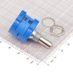
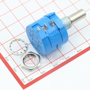
Bushing mount Optional AR pin feature Plastic or metal shaft and bushings Wirewound Solder lugs or PC pins Sealable (Full body seal)
■
Designed for use in HMI applications
*R
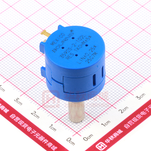
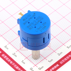
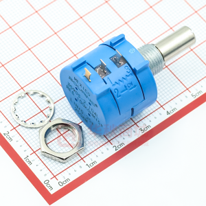
3590 - Precision Potentiometer
Electrical Characteristics1
Standard Resistance Range........................................................................................200 to 100 K ohms Total Resistance Tolerance................................................................................................................±5 % Independent Linearity...................................................................................................................±0.25 % Effective Electrical Angle ...............................................................................................3600 ° +10 °, -0 ° Absolute Minimum Resistance .....................................1 ohm or 0.1 % maximum (whichever is greater) Noise .................................................................................................................100 ohms ENR maximum Dielectric Withstanding Voltage (MIL-STD-202, Method 301) Sea Level ..............................................................................................................1,500 VAC minimum Power Rating (Voltage Limited By Power Dissipation or 450 VAC, Whichever is Less) +40 °C ........................................................................................................................................2 watts +125 °C........................................................................................................................................0 watt Insulation Resistance (500 VDC) ......................................................................1,000 megohms minimum Resolution .............................................................................................See recommended part numbers
5.08 ± .38 (.200 ± .015) 5.08 ± .38 (.200 ± .015) 6.99 ± .38 (.275 ± .015)
1 2
3
10.31 + .00/- .13 (.406+.000/-.005) BUSHING DIAMETER (SEE PART NUMBERS) .81 (.032) SHAFT DIAMETER (SEE PART NUMBERS)
.25 (.010) 7.92 (.312) 18.6 ± .4 (.732 ± .015) STANDOFFS 15.54 R (.612)
Environmental Characteristics
1
Operating Temperature Range .......................................................................................+1 °C to +125 °C Storage Temperature Range .........................................................................................-55 °C to +125 °C Temperature Coefficient Over Storage Temperature Range2 ...........................±50 ppm/°C maximum/unit Vibration..............................................................................................................................................15 G Wiper Bounce ...............................................................................................0.1 millisecond maximum Shock..................................................................................................................................................50 G Wiper Bounce ...............................................................................................0.1 millisecond maximum Load Life ...................................................................................................................1,000 hours, 2 watts Total Resistance Shift...................................................................................................±2 % maximum Rotational Life (No Load)................................................................................1,000,000 shaft revolutions Total Resistance Shift...................................................................................................±5 % maximum Moisture Resistance (MIL-STD-202, Method 103, Condition B) Total Resistance Shift...................................................................................................±2 % maximum IP Rating Sealed Versions (-3, -4, -7, and -8) ...............................................................................................IP 65 Unsealed Versions (-1 -2, -5, and -6) ............................................................................................IP 40
1.19 (PLASTIC VERSIONS) (.047) .81 ± .25 (METAL VERSIONS) (.032 ± .010) 20.62 ± .81 (.812 ± .032) 12.2 (.48)
11.81 (.465) 22 ± .38 DIA. (.875 ±.015) 12.70 DIA. (.500) MOUNTING SURFACE
Mechanical Characteristics
1
Stop Strength .............................................................................................45 N-cm (64 oz.-in.) minimum Mechanical Angle...........................................................................................................3600 ° +10 °, -0 ° Torque (Starting & Running).................................................0.35 N-cm (0.5 oz.-in.) maximum (unsealed) 1.1 N-cm (1.5 oz.-in.) maximum (sealed) Mounting ............................................................................................55-80 N-cm (5-7 lb.-in.) (plastic) 170-200 N-cm (15-18 in.-lb.) (metal) Shaft Runout ......................................................................................................0.13 mm (0.005 in.) T.I.R. Lateral Runout....................................................................................................0.20 mm (0.008 in.) T.I.R. Shaft End Play ...................................................................................................0.25 mm (0.010 in.) T.I.R. Shaft Radial Play................................................................................................0.13 mm (0.005 in.) T.I.R. Pilot Diameter Runout........................................................................................0.08 mm (0.003 in.) T.I.R. Backlash ............................................................................................................................1.0 ° maximum Weight ........................................................................................................................Approximately 19 G Terminals ................................................................................................................Solder lugs or PC pins Soldering Condition Manual Soldering ..............................................................96.5Sn/3.0Ag/0.5Cu solid wire or no-clean rosin cored wire; 370 °C (700 °F) max. for 3 seconds Wave Soldering ........................96.5Sn/3.0Ag/0.5Cu solder with no-clean flux; 260 °C (500 °F) max. for 5 seconds Wash processes ......................................................................................................Not recommended Marking......................................................Manufacturer’s name and part number, resistance value and tolerance, linearity tolerance, wiring diagram, and date code. Ganging (Multiple Section Potentiometers) .....................................................................1 cup maximum Hardware...........................One lockwasher and one mounting nut is shipped with each potentiometer.
NOTE: For Anti-rotation pin add 91 after configuration dash number. Example: -2 becomes -291 to add AR pin.
RECOMMENDED PC BOARD MOUNTING HOLE LOCATIONS HOLE DIAMETER FMS 2.08 (.082) CCW CW 2 1 3 CW 5.08 5.08 6.99 (.200) (.200) (.275) TOLERANCES: EXCEPT WHERE NOTED .51 .13 DECIMALS: .XX ± .XXX ± (.02), (.005) FRACTIONS: ±1/64 MM DIMENSIONS: (IN.)
Recommended Part Numbers
Resistance (Ω) 1,000 2,000 5,000 10,000 20,000 50,000 100,000 Resolution (%) .029 .023 .025 .020 .019 .013 .009
SHAFT & BUSHING CONFIGURATIONS (Bushing - DxL, Shaft - D) (-1) Plastic Bushing (3/8 ” x 5/16 ”) and Shaft (.2480 + .001, - .002) (-2) Metal Bushing (3/8 x 5/16 ) and Shaft (.2497 + .0000, - .0009) (-3) Sealed, Plastic Bushing (3/8 ” x 5/16 ”) and Shaft (.2480 + .001, - .002) (-4) Sealed, Metal Bushing (3/8 ” x 5/16 ”) and Shaft (.2497 + .0000, - .0009) (-5) Metric, Plastic Bushing (9 mm x 7.94 mm) and Shaft (6 mm + 0, - .076 mm) (-6) Metric, Metal Bushing (9 mm x 7.94 mm) and Shaft (6 mm + 0, - .023 mm) (-7) Metric, Sealed, Plastic Bushing (9 mm x 7.94 mm) and Shaft (6 mm + 0, - .076 mm) (-8) Metric, Sealed, Metal Bushing (9 mm x 7.94 mm) and Shaft (6 mm + 0, - .023 mm)
(Printed Circuit) 3590P-2-102L 3590P-2-202L 3590P-2-502L 3590P-2-103L 3590P-2-203L 3590P-2-503L 3590P-2-104L
(Solder Lug) 3590S-2-102L 3590S-2-202L 3590S-2-502L 3590S-2-103L 3590S-2-203L 3590S-2-503L 3590S-2-104L
(Solder Lug) 3590S-1-102L 3590S-1-202L 3590S-1-502L 3590S-1-103L 3590S-1-203L 3590S-1-503L 3590S-1-104L
BOLDFACE LISTINGS ARE IN STOCK AND READILY AVAILABLE THROUGH DISTRIBUTION. FOR OTHER OPTIONS CONSULT FACTORY. TERMINALS: L = RoHS COMPLIANT BLANK = STANDARD
REV. 06/06 *RoHS Directive 2002/95/EC Jan 27 2003 including Annex Specifications are subject to change without notice. Customers should verify actual device performance in their specific applications.
�