oH
VE S CO
AV R M
AI SIO PL
LA N IA
BL S NT
E
Features
■
*R
■
■
■
Integrates capacitor function in one
package
Lead free versions available (see How to
Order “Terminations” option)
RoHS compliant (lead free version)*
Design reduces termination noise
■
■
■
Popular standard capacitance values
available
Isolated, bussed and dual-bussed circuits
available
High temperature lead attachment to
withstand reflow temperatures up
to 260 °C
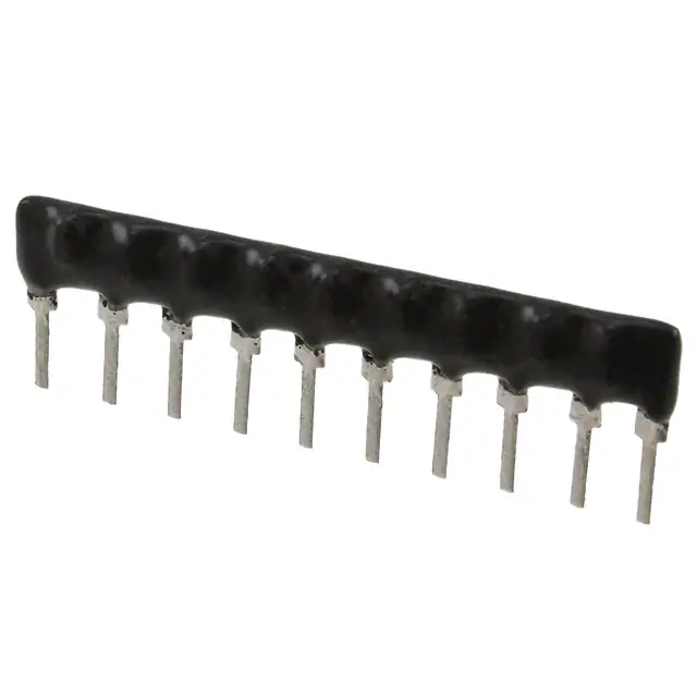
900 Series - Capacitor Networks
Electrical Characteristics
Capacitance Tolerance
39 pF - 270 pF............................±10 %
>270 pF - 0.1 µF.........................±20 %
Circuit Configuration .....Isolated, bussed
and dual-bussed
Capacitor Dielectric.................NPO, X7R
Capacitance Voltage Rating
39 pF - 270 pF
.............................NPO - 50V @ +25 °C
>270 pF - 0.047 µF
..............................X7R - 50V @ +25 °C
Physical Characteristics
Lead Spacing ..............0.100 ” (2.54 mm)
Lead Coating ..............tin-lead or tin only
(see How to Order)
Body Material
....Epoxy/Anhydride conformal material
Product Dimensions
Isolated Capacitors (902 Circuit)
A
MAXIMUM
1
PIN #1
REF.
MAX. 1.24
BOTH ENDS (.049)
.508 ± .050
TYP.
(.020 ± .002)
2.54 ± .07
(.100 ± .003*)
TYP.
NON-ACCUM.
3.43 + .38/ - .25
(.135 + .015/ - .010)
How To Order
46 10 M - 901 - 103 __
Model
(46 = SIP Pkg)
4
6
10
12
14
These models incorporate 2 to 7
isolated capacitors of equal value, each
connected between two pins.
Bussed Capacitors (901 Circuit)
Pin
Count
A Maximum
mm (Inches)
4
5
6
7
8
9
10
11
12
13
14
10.11 (.398)
12.65 (.498)
15.19(.598)
17.73 (.698)
20.27 (.798)
22.81 (.898)
25.35 (.998)
27.89 (1.098)
30.43 (1.198)
32.97 (1.298)
35.51 (1.398)
3.81
MAX.
(.150)
.254 ± .050
TYP.
(.010 ± .002 )
Standard High Volume Part Numbers
4610M-901-103
4610M-902-103
4610M-901-104
4610M-902-104
...
6.35
(.250)
MAX.
1
14
These models incorporate 3 to 13
capacitors of equal value, each
connected between a common bus
(Pin 1) and a separate pin.
Dual-Bussed Capacitors (904 Circuit)
Typical Part Marking
1
PART
NUMBER
CIRCUIT
4610M - 901
- 103
YYWW
PIN ONE
INDICATOR
n-1 n
These models incorporate 2 to 12
capacitors of equal value, each
connected to a dual buss that connects
Pin 1 to the last pin.
CAPACITANCE
CODE
DATE CODE
MANUFACTURER'S
TRADEMARK
Number of Pins
Profile
(M = Medium Profile)
Electrical Configuration
• 901 = Bussed
• 902 = Isolated
• 904 = Dual-Bussed
Capacitance Code
• First 2 digits are significant
• Third digit represents the
number of zeros to follow
Terminations
LF = Lead free (tin-plated)
Blank = Tin-lead plated
Consult factory for other available options.
Standard Capacitance Values and Codes
These are the standard and non-standard capacitance values available. Consult factory for
capacitance values and types outside this range. Tolerances of 5 %, 10 % and 20 % are available.
“NPO” DIELECTRICS
10 % Tolerance
Capacitance
(pF)
39
47
56
68
82
100
120
150
180
220
270
“X7R” DIELECTRICS
20 % Tolerance
Capacitance
Code
Capacitance
(pF)
Capacitance
Code
390
470
560
680
820
101
121
151
181
221
271
330
390
470
560
680
820
1000
1200
1500
1800
2200
2700
3300
3900
4700
5600
6800
8200
331
391
471
561
681
821
102
122
152
182
222
272
332
392
472
562
682
822
“X7R” DIELECTRICS
20 % Tolerance
Capacitance
µF)
(µ
0.01
0.012
0.015
0.018
0.022
0.027
0.033
0.039
0.047
0.056
0.068
0.082
0.1
Capacitance
Code
103
123
153
183
223
273
333
393
473
563
683
823
104
REV. 02/06
*RoHS Directive 2002/95/EC Jan 27 2003 including Annex
Specifications are subject to change without notice.
Customers should verify actual device performance in their specific applications.
�
很抱歉,暂时无法提供与“4610M-901-102”相匹配的价格&库存,您可以联系我们找货
免费人工找货- 国内价格
- 1+34.00920
- 200+13.57560
- 500+13.12200
- 1000+12.89520