■ RoHS compliant* (see How to Order
4
8
2
LF
P
6
1 2 33
8 1
–6 C1
VE *Ro
AE RSI HS
C- ON CO
Q2 S M
00 AV PLI
QU AIL AN
AL AB T
L
IF
IE E
D
Features
“Termination” option)
■ Standard E.I.A. package compatible with
automatic placement equipment
■ Tape and reel packaging standard
■ Custom circuits are available
■ Compliant leads to reduce solder joint
fatiguing
■ Standard electrical schematics: isolated,
bussed, dual terminator
■ Now available with improved tolerance to
±0.5 %
■ AEC-Q200 qualified
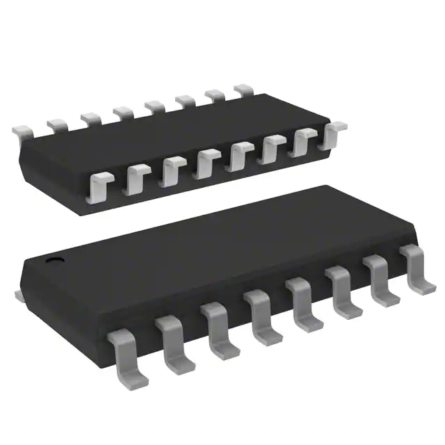
3312 - 2 mm SMD Trimming
Potentiometer
4800P Series
- Thick Film Surface Mount Medium Body
Environmental Characteristics
TESTS PER MIL-STD-202 ...... ∆R MAX.
Short Time Overload..................±0.25 %
Load Life ....................................±1.00 %
Moisture Resistance ..................±0.50 %
Resistance to Soldering Heat ....±0.25 %
Thermal Shock ..........................±0.25 %
Package Power Temp. Derating Curve
1.4
1.2
1.0
7.62 ± .25
(.300 ± .010)
.6
.4
.2
25
0
70
125
AMBIENT TEMPERATURE ( ° C )
Package Power Rating at 70 °C
4814P .....................................1.12 watts
4816P .....................................1.28 watts
4818P .....................................1.44 watts
4820P .....................................1.60 watts
Typical Part Marking
Represents total content. Layout may
vary.
RoHS COMPLIANCY
INDICATOR
PART
NUMBER
4816P LF
2-682
CYYWW
PIN ONE
INDICATOR
RESISTANCE CODE
13.72 ± .12
(.540 ± .005)
12.45 ± .12
(.490 ± .005)
11.18 ± .12
(.440 ± .005)
9.91 ± .12
(.390 ± .005)
1.27 ± .076
TYP.
(.050 ± .003*)
.13 + .12/ - .00
(.005 + .005/ - .000)
2.03 ± .12
(.080 ± .005)
R = .008" TYP.
.305 + .000/ - .101
(.012 + .000/ - .004)
8° MAX.
.611 ± .101
(.024 ± .004)
DATE CODE
MANUFACTURER'S
TRADEMARK
COUNTRY OF MANUFACTURE
(C = COSTA RICA)
Recommended Land Pattern
How To Order
Lead coplanarity .102mm (.004 inch) max. at mounting surface.
Governing dimensions are in metric. Dimensions in parentheses
are inches and are approximate.
*Terminal centerline to centerline measurements made at point of
emergence of the lead from the body.
2.0
TYP.
(.079)
48 16 P - 1 - 103 __ __
Model
(48 = SOM Pkg.)
Number of Pins
Electrical Configuration
• 1 or 4 = Isolated*
• 2 = Bussed*
• 3 = Dual Terminator*
Resistance Code
• First 2 digits are significant
• Third digit represents the
number of zeros to follow.
Resistance Tolerance
• Blank = ±2 % (see “Resistance Tolerance”
on next page for resistance range)
• F = ±1 % (100 ohms - 1 megohm)
• D = ±0.5 % (100 ohms - 1 megohm)
Terminations
• All electrical configurations EXCEPT T03:
LF = RoHS compliant
• ONLY electrical configuration T03:
L = RoHS compliant
• Blank = Tin/Lead-plated
*For tube packaging, use T01, T02, T03 or T04.
Consult factory for other available options.
.432 ± .076
TYP.
(.017 ± .003)
.8
CIRCUIT
Physical Characteristics
Flammability ........ Conforms to UL94V-0
Lead Frame Material
.........................Copper, solder coated
Body Material................... Thermoplastic
Product Dimensions
5.59 ± .12
(.220 ± .005)
4820P
4818P
4816P
4814P
1.6
WATTS
Product Characteristics
Resistance Range
................... 10 ohms to 2.2 megohms
Maximum Operating Voltage ...........50 V
Temperature Coefficient of Resistance
50 Ω and above..............±100 ppm/°C
below 50 Ω .....................±250 ppm/°C
TCR Tracking
(for equal values within a package)
.....50 ppm/°C max. for values > 50 Ω;
.............100 ppm/°C for values ≤ 50 Ω
Operating Temperature
................................-55 °C to +125 °C
Insulation Resistance
........................ 10,000 megohms min.
Dielectric Withstanding Voltage
...........................................200 VRMS
Lead Solderability .....Meet requirements
of MIL-STD-202 Method 208
1.27
TYP.
(.050)
.63
TYP.
(.025)
1
2
3
4
5
6
7
8
9
10
20
19
18
17
16
15
14
13
12
11
8.9
(.350)
SOM-14
8.26 SOM-16 SOM-18
9.53
(.325)
10.80 SOM-20
(.375)
(.425) 12.07
(.475)
4.9
(.193)
NOTE: Land pattern dimensions are based on
design rules established by the Institute for Interconnecting and Packaging Electronic Circuits in
IPC-SM-782.
For Standard Values Used in
Capacitors, Inductors, and Resistors,
click here.
*RoHS Directive 2002/95/EC Jan. 27, 2003 including annex and RoHS Recast 2011/65/EU June 8, 2011.
Specifications are subject to change without notice.
The device characteristics and parameters in this data sheet can and do vary in different applications and actual device performance may vary over time.
Users should verify actual device performance in their specific applications.
�For information on specific applications,
download Bourns’ application notes:
■ DRAM Applications
■ Dual Terminator Resistor Networks
■ R/2R Ladder Networks
■ SCSI Applications
3312 -Series
2 mm- Thick
SMDFilm
Trimming
4800P
Surface Potentiometer
Mount Medium Body
Isolated Resistors (1 and 4 Circuits)
Model 4814P-1
Model 4816P-1 (Shown)
Model 4818P-1
Model 4820P-1
16
15
14
13
12
11
10
Bussed Resistors (2 Circuit)
Model 4814P-2
Model 4816P-2 (Shown)
Model 4818P-2
Model 4820P-2
9
16
15
14
13
12
11
Dual Terminator (3 Circuit)
Model 4814P-3
Model 4816P-3 (Shown)
Model 4818P-3
Model 4820P-3
10
16
9
9
R1
R1
R2
R3
R4
R5
R6
R7
R8
R15
R14
R13
R12
R11
R10
R1
R2
1
2
3
4
5
6
7
8
R1
Model 4816P-4 (Shown)
Model 4820P-4
16
15
14
R8
R1
1
13
12
R7
3
11
10
R6
R2
2
1
5
2
R3
3
R4
R5
4
5
R6
6
R7
R8
7
R1
R1
R1
R1
8
R1
R2
R2
R1
R2
R2
R1
R2
R2
R1
R2
R2
R2
R1
R2
R1
R2
R2
R1
R2
1
9
8
R5
R3
4
R2
R1
R9
R4
6
7
8
Resistance Tolerance
10 ohms to 49 ohms ................... ±1 ohm
50 ohms to 2.2 megohms ............. ±2 %*
Power Rating per Resistor
1 Circuit at 70 °C .................. 0.160 watt
4 Circuit at 70 °C .................. 0.160 watt
Resistance Tolerance
10 ohms to 49 ohms ................... ±1 ohm
50 ohms to 2.2 megohms ............. ±2 %*
Power Rating per Resistor
2 Circuit at 70 °C .................. 0.080 watt
Resistance Tolerance
Below 100 ohms ...................... ±2 ohms
100 ohms to 2.2 megohms ........... ±2 %*
Power Rating per Resistor
3 Circuit at 70 °C .................. 0.080 watt
Resistor Power Temp. Derating Curve
Resistor Power Temp. Derating Curve
Resistor Power Temp. Derating Curve
.225
.225
.200
.200
.200
.175
.175
.175
.150
.150
.150
WATTS
WATTS
WATTS
.225
.125
.125
.125
.100
.100
.100
.075
.075
.075
.050
.050
.050
.025
.025
0
25
70
AMBIENT TEMPERATURE (°C)
.025
25
0
125
70
125
Code
100
220
270
330
390
470
560
680
820
101
121
151
Ohms
180
220
270
330
390
470
560
680
820
1,000
1,200
1,500
Code
181
221
271
331
391
471
561
681
821
102
122
152
Ohms
1,800
2,000
2,200
2,700
3,300
3,900
4,700
5,600
6,800
8,200
10,000
12,000
Code
182
202
222
272
332
392
472
562
682
822
103
123
Ohms
15,000
18,000
20,000
22,000
27,000
33,000
39,000
47,000
56,000
68,000
82,000
100,000
25
70
125
AMBIENT TEMPERATURE ( °C )
Popular Resistance Values (3 Circuit)**
Popular Resistance Values (1, 4 and 2 Circuits)**
Ohms
10
22
27
33
39
47
56
68
82
100
120
150
0
AMBIENT TEMPERATURE ( °C )
Code
153
183
203
223
273
333
393
473
563
683
823
104
Ohms
120,000
150,000
180,000
220,000
270,000
330,000
390,000
470,000
560,000
680,000
820,000
1,000,000
Code
124
154
184
224
274
334
394
474
564
684
824
105
* Add “F” after resistance code for ±1 % tolerance available from 100 Ω through 1M Ω, or add “D”
after resistance code for ±0.5 % tolerance available from 100 Ω through 1M Ω.
Part number suffix examples: -103 = 10K Ω, ±2 %; -103F = 10K Ω, ±1 %; -103D = 10K Ω, ±0.5 %
** Non-standard values available, within resistance range.
Resistance
Ohms
R1
160
180
220
220
330
330
3,000
Code
R2
240
390
270
330
390
470
6,200
R1
161
181
221
221
331
331
302
R2
241
391
271
331
391
471
622
REV. 04/15
Specifications are subject to change without notice.
The device characteristics and parameters in this data sheet
can and do vary in different applications and actual device
performance may vary over time.
Users should verify actual device performance
in their specific applications.
�3312Mount
- 2 mmOrdering
SMD Trimming
Surface
Guide Potentiometer
*Circuit Codes
Electrical
Configuration
Tape & Reel
Tubes
Isolated
1
T01
Bussed
2
T02
Dual Terminated
3
T03
Adj. Isolated
4
T04
Examples
4816P-1-101
Isolated Circuit in Tape & Reel Package
4816P-T01-101
Isolated Circuit in Slide Tube Package
*4816P-X-RC: To specify package type, replace “X” with appropriate “Circuit Code”.
W
F
POLYSTYRENE REEL
(ANTI-STATIC)
DIRECTION
OF FEED
T
1.5 + .10/ - .00
(.059 + .004/ - .00)
DIA.
1.5
(.059)
MIN.
20.2
MIN.
(.795)
13.0 ± .20
(.512 ± .008)
1.5
MIN. DIA.
(.059)
4.0 ± .10
(.157 ± .004)
12.0 ± .10
(.472 ± .004)
CARRIER TAPE
STATIC DISSIPATIVE
330.2
MAX.
(13.0)
COVER TAPE
(ANTISTATIC)
NOTE: DIMENSIONS NOT SPECIFIED ARE PER EIA RS-481-2.
DIMENSIONS:
Model
MM
(IN)
V
Standard Quantity
per Reel
Carrier Tape Width
(W)
Cover Tape Width
(W)
Reel Width
(T)
Pocket Center
(F)
2,000
24.0 ± .30
(.945 ± .012)
21.0
(.827) NOM.
30.4
MAX.
(1.197)
11.5 ± .10
(.453 ± .004)
4814P
4816P
4818P
4820P
Leader Length = 500 min.
Trailer Length = 500 mm min.
}
Empty Component Pockets
Sealed with Cover Tape
Specifications are subject to change without notice.
The device characteristics and parameters in this data sheet can and do vary in different applications and actual device performance may vary over time.
Users should verify actual device performance in their specific applications.
�